Circuit Description—434
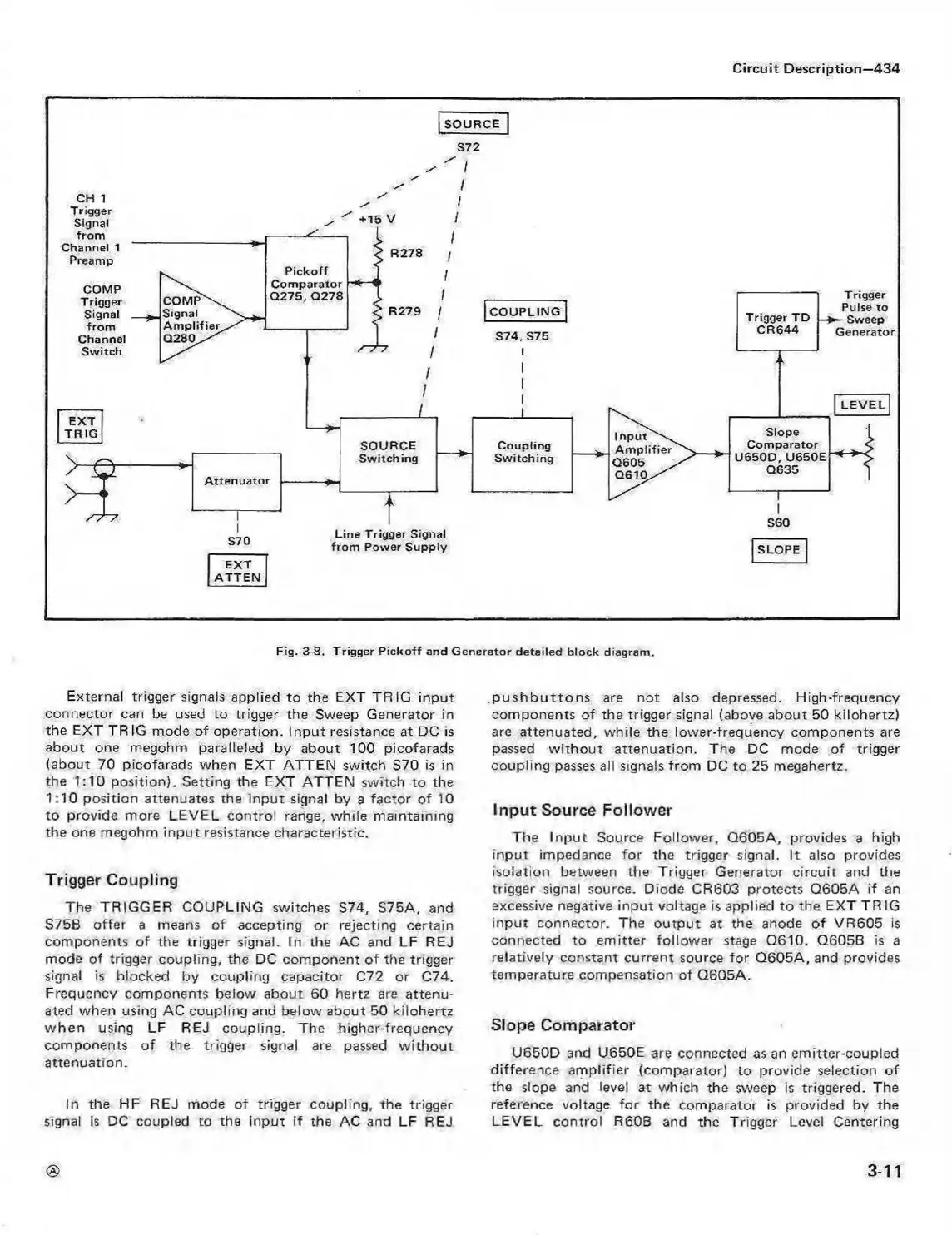
Fig. 3-8. T rig ge r P ic k o ff an d G e n e ra to r de ta ile d b lo c k diag ram .
External trigger signals applied to the EXT TRIG input
connector can be used to trigger the Sweep Generator in
the EXT TR 1G mode of operation. Input resistance at DC is
about one megohm paralleled by about 100 picofarads
(about 70 picofarads when EXT ATTEN switch S70 is in
the 1:10 position). Setting the EXT ATTEN switch to the
1:10 position attenuates the input signal by a factor of 10
to provide more LEVEL control range, while maintaining
the one megohm input resistance characteristic.
Trigger Coupling
The TRIGGER COUPLING switches S74, S75A, and
S75B offer a means of accepting or rejecting certain
components of the trigger signal. In the AC and LF REJ
mode of trigger coupling, the DC component of the trigger
signal is blocked by coupling capacitor C72 or C74.
Frequency components below about 60 hertz are attenu
ated when using AC coupling and below about 50 kilohertz
w hen using LF REJ coupling. The higher-frequency
components of the trigger signal are passed w ithout
attenuation.
In the HF REJ mode of trigger coupling, the trigger
signal is DC coupled to the input if the AC and LF REJ
p u s h b u tto n s are not also depressed. High-frequency
components o f the trigger signal (above about 50 kilohertz)
are attenuated, while the lower-frequency components are
passed w ith ou t attenuation. The DC mode of trigger
coupling passes all signals from DC to 25 megahertz.
Input Source Follower
The Input Source Follower, Q605A, provides a high
input impedance for the trigger signal. It also provides
isolation between the Trigger Generator circuit and the
trigger signal source. Diode CR603 protects Q605A if an
excessive negative input voltage is applied to the EXT TRIG
input connector. The output at the anode of VR605 is
connected to em itter follow er stage Q610. Q6058 is a
relatively constant current source for Q605A, and provides
temperature compensation of Q605A.
Slope Comparator
U650D and U650E are connected as an emitter-coupled
difference am plifier (comparator) to provide selection of
the slope and level at which the sweep is triggered. The
reference voltage for the comparator is provided by the
LEVEL control R60B and the Trigger Level Centering
3-11
 Loading...


