Maintenance—434
Circuit Boards. Figs. 8-1 through 8-23 in the Diagrams
section show the c ircu it boards used in the 434. Fig. 4-5
shows the location o f each board w ith in the instru
ment. Each electrical com ponent on the boards is id e n ti
fied by its circ u it number. These pictures, used along
w ith the diagram s, aid in locating the com ponents m ounted
on the c irc u it boards.
Wiring Color-Code. A ll insulated w ire and cable used in
the 434 is color-coded to fa cilita te c ircu it tracing. Table 4-1
gives the w irin g color-code fo r the power-supply voltages
used in this instrum ent.
TABLE 4-1
Power Supply Wiring Color Code
Supply
Background
Color
Stripe
— 15 vo lt Purple
Black
+ 15 vo lt Red
Black
+ 115 vo lt Red
B row n
+250 v o lt Red
Orange
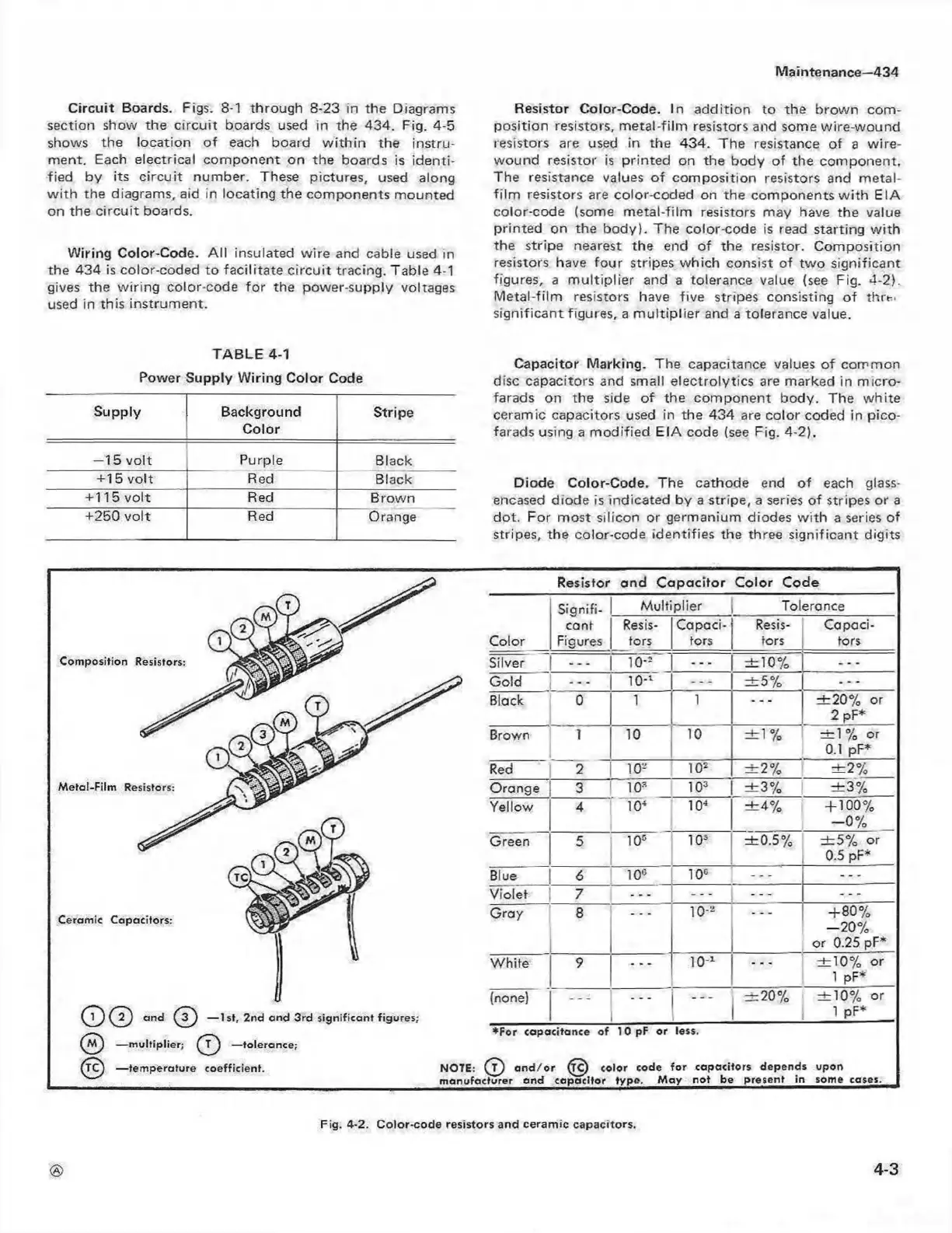
Resistor Color-Code. In ad d ition to the brow n com
position resistors, m etal-film resistors and some w ire-w ound
resistors are used in the 434. The resistance o f a w ire-
wound resistor is printed on the body of the com ponent.
The resistance values o f com position resistors and metal-
film resistors are color-coded on the com ponents w ith EIA
color-code (some m etal-film resistors may have the value
prin ted on the body). The color-code is read starting w ith
the stripe nearest the end of the resistor. C om position
resistors have fo ur stripes w hich consist of tw o significant
figures, a m u ltip lie r and a tolerance value (see Fig. 4-2).
M etal-film resistors have five stripes consisting o f thrt-'
significant figures, a m u ltip lie r and a tolerance value.
Capacitor Marking. The capacitance values o f com m on
disc capacitors and small electrolytics are marked in m icro
farads on the side o f the com ponent body. The w hite
ceram ic capacitors used in the 434 are color coded in pico
farads using a m odified EIA code (see Fig. 4-2).
Diode Color-Code. The cathode end o f each glass-
encased diode is indicated by a stripe, a series o f stripes or a
dot. For m ost silicon or germanium diodes w ith a series of
stripes, the color-code identifies the three significant digits
Com position Resistors:
M etal-Film Resistors:
Ceramic Capacitors:
Resistor and Capacitor Color Code
O © © — 1st, 2nd and 3 rd significa nt figun
© — m ultiplier; ( J ) — tolerance;
— tem perature coefficient.
Color
Signifi
cant
Figures
M ultiplier
Tolerance
Resis
tors
Capaci
tors
Resis
tors
Capaci
tors
Silver
. . .
io-= ± 1 0 %
—
Gold
—
10-*
—
± 5 %
Black 0
1
1
—
± 2 0 % or
2 pF*
Brown 1 10 10
± 1 %
± 1 % or
0.1 pF*
Red
2
10-
102
± 2 %
± 2 %
Orange
3 1.0*
103
± 3 %
± 3 %
Yellow
4
104
104
± 4 %
+ 100%
- 0 %
Green
5
105
105
± 0 .5 %
± 5 % or
0.5 pF*
Blue 6
10°
10°
—
Violet
7
—
. . .
Gray
8
10--
+ 80 %
-2 0 %
or 0.25 pF*
W hite 9
10-1
± 1 0 % or
1 pF*
(none)
± 2 0 % ± 1 0 % or
1 pF*
♦ For capacitance o f 10 pF or less.
NOTE: ( T ) a n d /o r ^C ) color code fo r capacitors depends upon
m anufacturer and capacitor type . M ay no t be present in some cases.
4-3
Fig. 4-2. C o lo r-cod e resistors and ce ram ic cap acitors.
 Loading...


