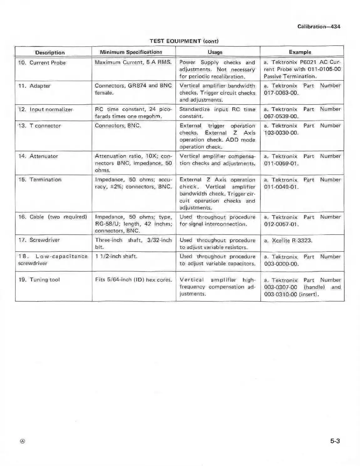
TEST EQUIPMENT (cont)
Calibration—434
Description
Minimum Specifications
Usage Example
10. Current Probe
Maximum Current, 5 A RMS.
Power Supply checks and
adjustments. Not necessary
for periodic recalibration.
a. Tektronix P6021 AC Cur
rent Probe w ith 011-0105-00
Passive Termination.
11. Adapter
Connectors, GR874 and BNC
female.
Vertical amplifier bandwidth
checks. Trigger circuit checks
and adjustments.
a. Tektronix Part Number
017-0063-00.
12. Input normalizer
RC time constant, 24 pico
farads times one megohm.
Standardize input RC time
constant.
a. Tektronix Part Number
067-0539-00.
13. T connector
Connectors, BNC.
External trigger operation
checks. External Z Axis
operation check. ADD mode
operation check.
a. Tektronix Part Number
103-0030-00.
14. Attenuator Attenuation ratio, 10X; con
nectors BNC, impedance, 50
ohms.
Vertical am plifier compensa
tion checks and adjustments.
a. Tektronix Part Number
011-0059-01.
15. Termination
Impedance, 50 ohms; accu
racy, ±2%; connectors, BNC.
External Z Axis operation
ch e ck . Vertical am plifier
bandwidth check. Trigger cir
cuit operation checks and
adjustments.
a. Tektronix Part Number
011-0049-01.
16. Cable (two required) Impedance, 50 ohms; type,
RG-58/U; length, 42 inches;
connectors, BNC.
Used throughout procedure
for signal interconnection.
a. Tektronix Part Number
012-0057-01.
17. Screwdriver
Three-inch shaft, 3/32-inch
bit.
Used throughout procedure
to adjust variable resistors.
a. Xcelite R-3323.
1 8 . L o w -c a p a c ita n c e
screwdriver
1 1/2-inch shaft.
Used throughout procedure
to adjust variable capacitors.
a. Tektronix Part Number
003-0000-00.
19. Tuning tool
Fits 5/64-inch (ID) hex cores.
V e rtic a l a m p lifie r high-
frequency compensation ad
justments.
a. Tektronix Part Number
003-0307-00 (handle) and
003-0310-00 (insert).
5-3
 Loading...


