Incoming Inspection
CSA7000B Series & TDS7000B Series Instruments User Manual
1-27
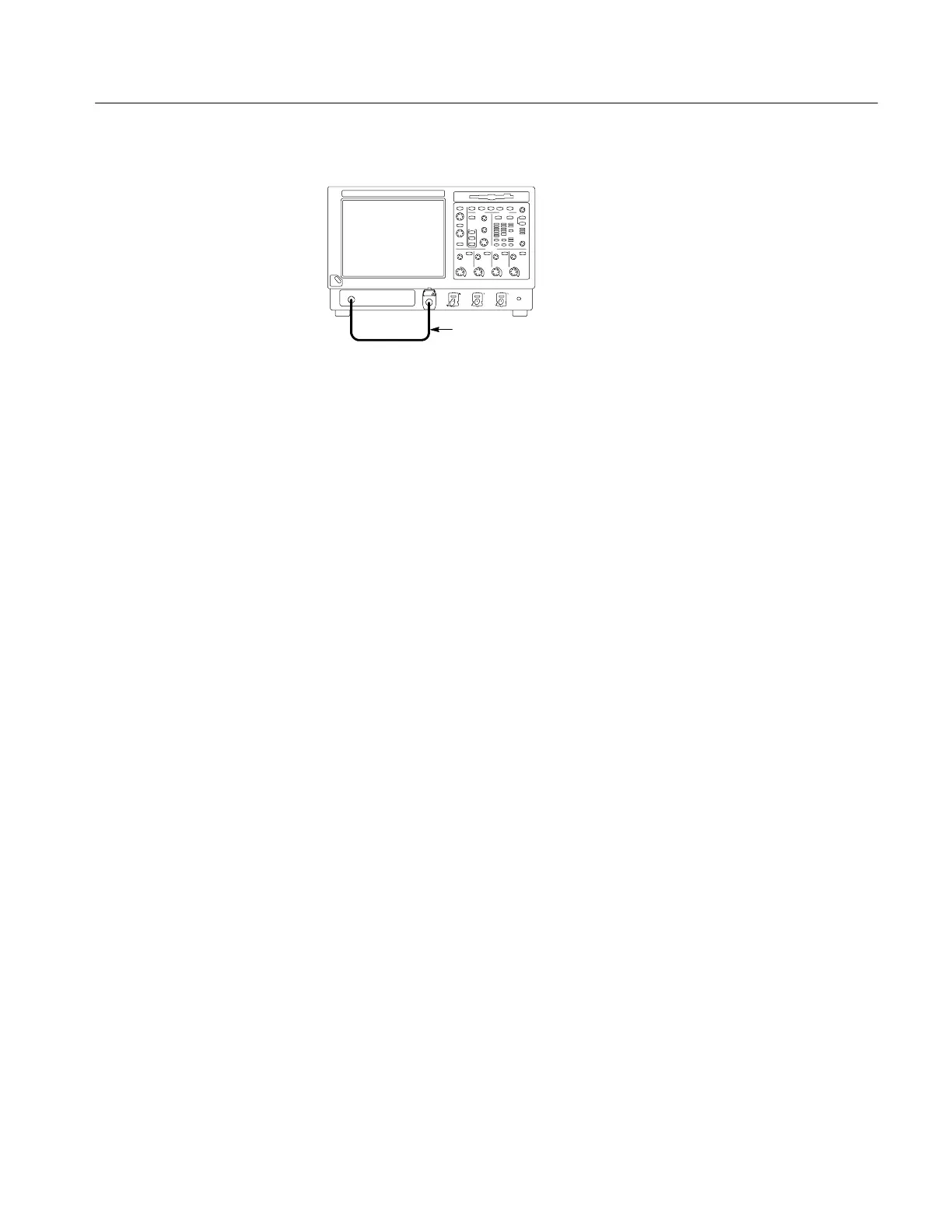
Instrument under test
BNC cable from PROBE
COMPENSATION output
to CH 1 input
Figure 1- 11: Setup for time base test
3. Set up the instrument: Push the front-panel AUTOSET button.
4. Touch the Vert button and then touch Offset. Adjust the Ch1 Offset to
--0.25 V using the multipurpose knob.
5. Set the Vertical SCALE to 100 mV per division.
6. Set the time base: Set the horizontal SCALE to 200 s/div. The time-base
readout is displayed at the bottom of the graticule.
7. Verify that the time base operates: Confirm the following statements.
H One period of the square-wave probe-compensation signal is about five
horizontal divisions on-screen for the 200 s/div horizontal scale setting.
H Rotating the horizontal SCALE knob clockwise expands the waveform
on-screen (more horizontal divisions per waveform period), counter-
clockwise rotation contracts it, and returning the horizontal scale to
200 s/div returns the period to about five divisions.
H The horizontal POSITION knob positions the signal left and right
on-screen when rotated.
8. Verify horizontal delay:
a. Center a rising edge on screen:
H Set the horizontal POSITION knob so that the rising edge where the
waveform is triggered is lined up with the center horizontal
graticule.
H Change the horizontal SCALE to 20 s/div. The rising edge of the
waveform should remain near the center graticule and the falling
edge should be off screen.
b. Turn on and set horizontal delay:

 Loading...


