Acquiring Waveforms
3-8
CSA7000B Series & TDS7000B Series Instruments User Manual
NOTE. This section describes how the vertical and horizontal controls define the
acquisition of live waveforms. These controls also define how all waveforms are
displayed, both live and derived waveforms (math waveforms, reference
waveforms, and so on). The sections that follow cover display-related usage:
H Displaying Waveforms on page 3--119.
H Creating and Using Math Waveforms on page 3--167.
Signal Connection and Conditioning
This section presents overviews of the instrument features related to setting up
the input signal for digitizing and acquisition. It addresses the following topics:
H How to turn on channels and adjust vertical scale, position, and offset
H How to set horizontal scale, position, and access record-length and trigger-
position controls
H How to get a basic trigger on your waveform
NOTE. Terminology: This manual uses the terms vertical acquisition window and
horizontal acquisition window throughout this section and elsewhere. These
terms refer to the vertical and horizontal range of the segment of the input signal
that the acquisition system acquires. The terms do not refer to any windows or
display windows on screen.
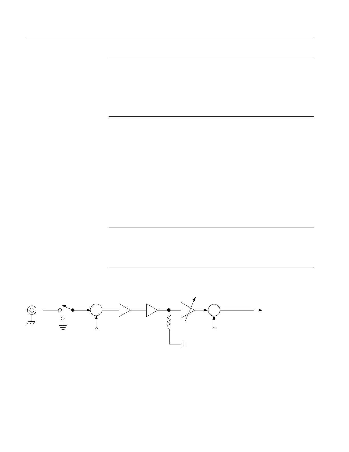
Figure 3--1 shows the model for each input channel.
+
---
+
+
Σ
Σ
Vertical
offset
Coupling
Input
termination
Vertical
scale
Vertical
position
To the
remainder
of the
acquisition
system
Bandwidth
limit
Scale = K1 * K2 * K3
External
attenuation
Probe
K1 K2 K3
50 Ω
Figure 3- 1: Input and Acquisition Systems and Controls

 Loading...


