Multi Pro 1750 Hydraulic SystemPage 4 − 29
Removing the Hydraulic Pump (Fig. 21)
1. Park the machine on a level surface, stop spray
pump, engage parking brake and stop engine. Remove
key from the ignition switch and tilt operator’s seat for-
ward.
CAUTION
Before disconnecting components or perform-
ing any work on hydraulic system, all pressure in
the system must be relieved (see Relieving Hy-
draulic System Pressure in the General Informa-
tion section of this chapter).
2. Label all hydraulic connections at gear pump for as-
sembly purposes. Thoroughly clean hydraulic hose
ends prior to disconnecting the hoses.
3. Disconnect suction hose from gear pump fitting. Al-
low hose and transaxle/reservoir to drain into a suitable
container.
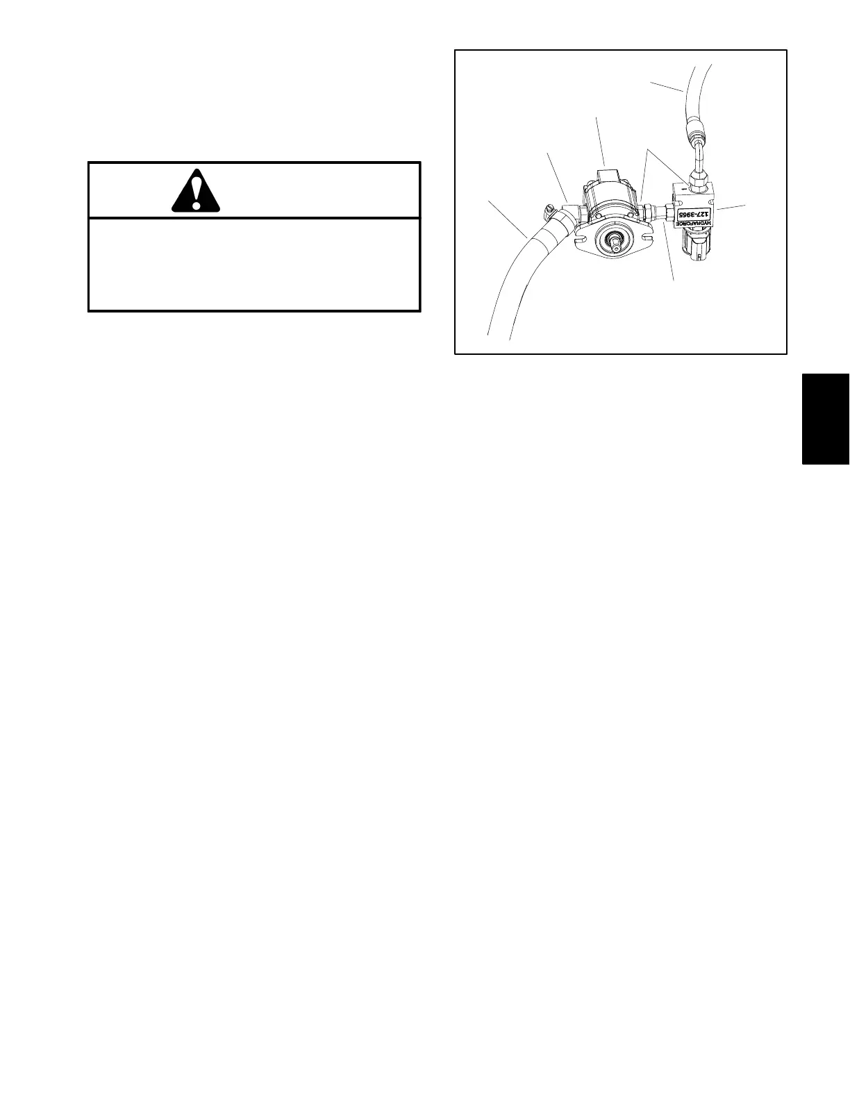
4. Disconnect hydraulic enable valve from pump.
Loosen swivel connector at fitting in gear pump
(Fig. 22).
5. Cap or plug openings of gear pump, enable valve,
and suction line to prevent contamination, and position
hydraulics enable valve assembly away from gear
pump.
6. Loosen two (2) square head set screws that secure
pump hub (item 12) to gear pump shaft.
7. Support gear pump to prevent it from falling.
8. Remove two (2) cap screws, flat washers and lock
nuts that secure gear pump to frame bracket.
9. Slide gear pump shaft from the pump hub and re-
move pump from the machine.
10.Locate and retrieve square key (item 9) from gear
pump shaft.
11.If hydraulic fittings are to be removed from gear
pump, mark fitting orientation to allow correct assembly.
Remove fittings from pump and discard O−rings.
1. Hydraulic pump
2. Hydraulics enable valve
3. Suction hose
4. Hose (to steering valve)
5. Swivel connector
6. Hydraulic fitting
7. Hydraulic fitting
Figure 22
2
1
3
5
4
6
7
Installing the Hydraulic Pump (Fig. 21)
1. If fittings were removed from gear pump, lubricate
and place new O−rings onto fittings. Install fittings into
port openings using marks made during the removal
process to properly orientate fittings. Tighten fittings
(see Hydraulic Fitting Installation in this chapter).
2. Position key into hydraulic pump shaft and apply an-
tiseize lubricant to pump shaft and key.
3. Align key in hydraulic pump shaft with the slot in the
pump hub (item 12) and slide gear pump shaft into the
pump hub.
4. Position hydraulic pump to the frame bracket and se-
cure pump with two (2) cap screws, flat washers and
lock nuts. Tighten lock nuts from 27 to 33 ft−lb (37 to 44
N−m).
5. Secure pump hub to gear pump shaft with two (2)
square head screws (item 11). Torque square head
screws from 90 to 110 in−lb (10.2 to 12.4 N−m).
6. Remove plugs and caps from hydraulic pump and
hydraulic lines that were installed during disassembly.
Connect suction hose and swivel connector at hy-
draulics enable valve to gear pump fittings (see Hydrau-
lic Hose and Tube Installation in this chapter).
7. Check fluid level in transaxle and adjust as required.
Hydraulic
System
 Loading...