OPERATOR’S MANUAL
series Robot Controller
5.4 Coordinate Data Directory Display Mode
The coordinate data directory display mode displays one (1) coordinate on one (1)
line at a time. In this mode, it is possible to add and delete the coordinate data.
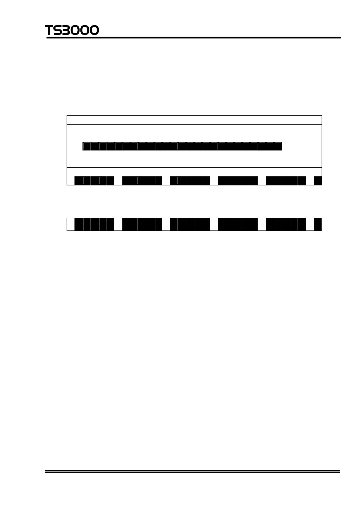
An example of display is given below.
T R A N S S E L E C T I O N [ 3 / 1 1 ]
. w o r l d 1 0
w T R A N S 0 0 0 0 1 0
T R A N S 0 0 0 0 2 5
t T R A N S 0 0 0 0 3 0
↓
T R A N S 0 0 0 0 4 4
T R A N S 0 0 0 0 2
S A V E P R G P Y L D W O R K T O O L >
Each time the NEXT key is pressed, the menu is changed over as follows:
< N O S A V F I N D C U T P A S T E
• An inversely displayed section in the data is called the "main cursor" which
indicates that this data is selected for editing.
• Symbol "↑" shown in the 1st column signifies that there is coordinate data before
the top data.
• Symbol "↓" shown in the 1st column signifies that there is coordinate data after
the final data.
• Alphabet "t" displayed in the 1st column represents that the coordinate data on
the same line is based on the tool coordinate system.
• Alphabet "w" displayed in the 1st column represents that the coordinate data on
the same line is based on the work coordinate system.
• On the right side of the coordinate name, the number of positional data belonging
to that coordinate is displayed.
• Regarding the data of [nnnn/mmmm] on the 1st line, "nnnn" identifies the
selected coordinate index, and "mmmm" the number of coordinate data.
STE 80720
– 5-49 –

 Loading...