OPERATOR’S MANUAL
series Robot Controller
5.6 Load Data Display Mode
The load data display mode displays the mass and center of gravity offset of a load
used to control the gain and acceleration. In this mode, it is possible to add, delete,
and change the load data.
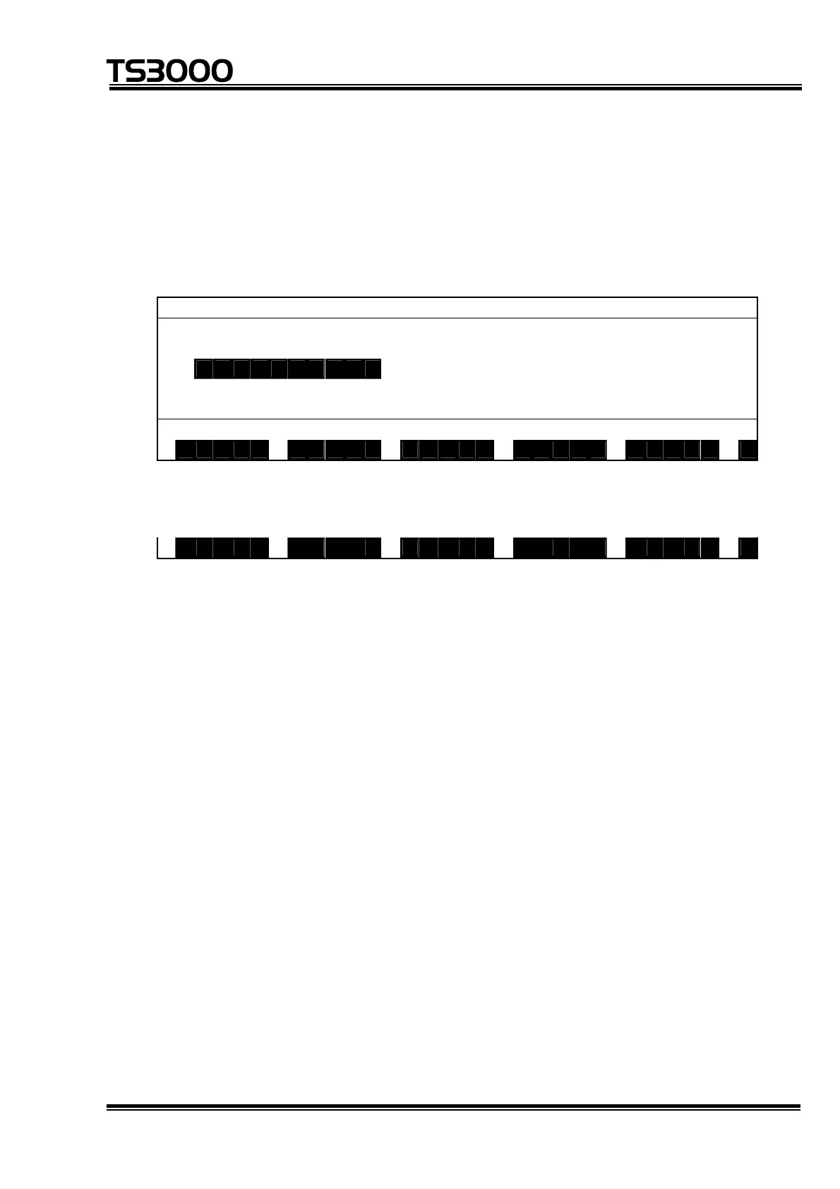
An example of the display is given below.
L O A D W E I G H T O F F S E T
↑
L O A D 0 0 0 0 0 3 = 1 0 0 . 0 0 0 , 1 0 0 . 0 0 0
L O A D 0 0 0 0 0 4 = 2 0 0 . 0 0 0 , 0 . 0 0 0
L O A D 0 0 0 0 0 5 = 50 . 000 , 0 . 000
L O A D 0 0 0 0 0 6 = 5 0 . 0 0 0 , 0 . 0 0 0
↓
L O A D 0 0 0 0 0 7 = 5 0 . 0 0 0 , 0 . 0 0 0
L O A D 0 0 0 0 0 5
S A V E P R G P O I N T T R A N S F I N D >
Each time the NEXT key is pressed, the menu is changed over as follows:
< N O S A V C U T P A S T E
• An inversely displayed section in the data is called the "main cursor" which
indicates that this data is selected for editing.
• Symbol "↑" shown in the 1st column signifies that there is load data before the
top data.
• Symbol "↓" shown in the 1st column signifies that there is load data after the final
data.
• "WEIGHT" represents the mass of a load (in kg).
• "OFFSET" represents the horizontal length (in mm) between the gravity center of
a load and the tool shaft center.
• The load data should include the tool own load.
STE 80720
– 5-80 –

 Loading...