Home
TSI Instruments
Controller
PRESSURA RPC30
TSI Instruments PRESSURA RPC30 User Manual
4
of 1
of 1 rating
133 pages
Give review
Manual
Specs
To Next Page
To Next Page
To Previous Page
To Previous Page
Loading...
Technical Section
19
Configure Menu
MENU ITEM
Monitor/
Controller
SOFTWARE
NAME
ITEM DESCRIPTION
ITEM RANGE
DEFAULT VALUE
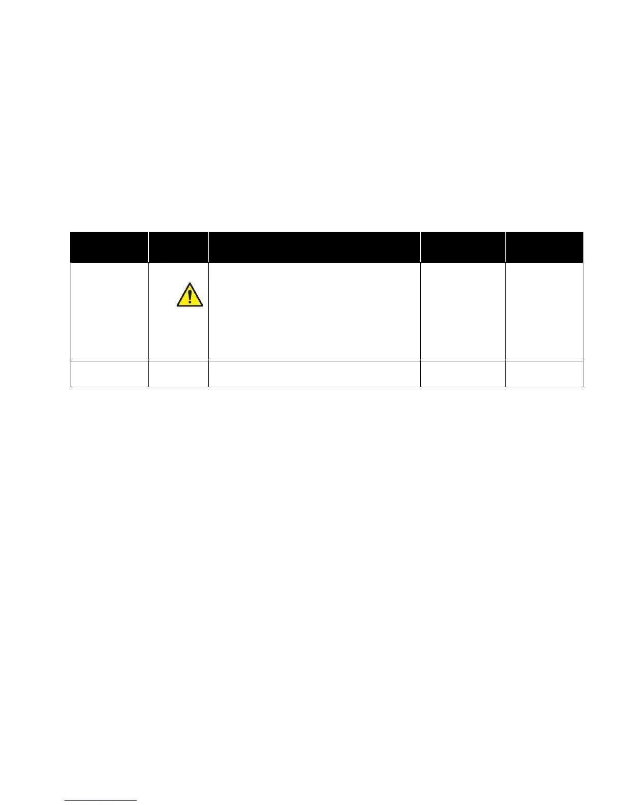
Configure INPUT7
Input
7
The
Input
7
item selects the desi
red input type for Input7.
Room1 Supply Air
Temperature,
Exhaust Pressure
Flow, Exhaust Linear
Flow, Exhaust
Venturi, Exhaust
Switch, Anteroom
Key Switch, None
None
Go to the
Input 7
menu to adjust param
eters such as
sensor range associated with Input7.
Input
7
can only be set to
ANTEROOM
KEYSWITCH
if
the
# of Rooms
item is set to
1 ROOM WITH ANTEROOM
.
Input
7
can only be set to
ROOM1 S
UPPLY AIR
TEMPERATURE
if
Ctrl Device
is set
to
EXHAUST/SUPPLY/TEMP
.
Number Format
Num Format
The
Num Format
menu item selects the
decimal point.
Period
Comma
Period
26
28
Table of Contents
Default Chapter
7
Table of Contents
7
Safety Information
9
Description of Caution Symbol
9
Access Code / Passcode
9
How to Use this Manual
9
User Basics
11
The Instrument
11
Useful User Information
11
Operator Panel
11
Part One
11
Display Screen
12
Room Indicator Colors
12
Operator Keys
12
MUTE Key
12
USB Port
13
Visual Alarm
13
Audible Alarms
13
Alarm Relays
14
Before Calling TSI
14
Technical Section
15
Pressura Room Pressure Controller
15
Part Two
15
Software Programming
16
Changing Room Mode
16
Main Running Screen
16
Room Mode Selection Screen
16
Entering Menus
17
Menus and Menu Items
17
Entering Data
17
Swipe to Access Menu System
17
Drop-Down Selection
18
Numeric Setpoints
18
Using a Drop-Down Selection
18
Entering Numeric Setpoints
18
Programming Example
19
Menu and Menu Items
20
Configure Menu
22
Number of Rooms Monitored
22
Devices Controlled
23
Label for Room 1
24
Label for Anteroom
24
Measurements Displayed
25
Display Average
25
Display Units
25
Configure INPUT1
25
Configure INPUT2
26
Configure INPUT3
26
Configure INPUT4
26
Configure INPUT5
26
Configure INPUT7
27
Number Format
27
Enable Access Codes
28
Mode of Room 1
29
Room 1 Alarm Enable
29
Room1 Alarm Menu
33
Anterm Alarm Menu
33
Anteroom Negative High Alarm
34
Anteroom Positive Low Alarm
34
Alarm Constraints
35
Rm1 Setpnts Menu
37
Alarm Config Menu
43
Alarm Reset
43
Enable Sound
43
Alarm Delay
43
Door Delay
44
Mute Timeout
44
Control Menu
45
Pressure Control Sensitivity
45
Flow Control Speed
45
Supply Control Direction
46
Temperature Control Direction
46
Temperature Throttling Range
46
Pressure and Flow Control Coefficients
47
Network Address
48
Mac ID
48
Baud Rate
48
Interface Menu
48
LON Configuration
49
Interface Menu
49
Analog Output Signal Type
50
Diagnostics Menu
53
Input1 Config Menu
54
TSI Sensor
54
Reset Calibration
54
Check Sensor Status
55
Press Trans
56
Set Sensor Zero Calibration
57
Set Sensor Span Calibration
57
Input3 Config Menu
61
Sup Pres Flow
61
Set Flow Station Duct Area
61
Sup Venturi
65
Minimum Flow
65
Maximum Flow
65
Supply Switch
66
Rm1 Dr Sw
66
Input4 Config Menu
67
Rm1 Occ Sen
67
Input5 Config Menu
67
Input6 Config Menu
68
Ant Occ Sen
68
Exh Pres Flow
70
Exh Lin Flow
72
Exh Switch
75
Ante Key Switch
75
Room Pressure Calibration
77
TSI (Through-The-Wall) Sensor Calibration
77
Pressure Transducer Calibration
77
Flow Calibration
78
Pressure Flow Station Calibration
78
Linear Flow Station Calibration
79
Venturi with Feedback Calibration
80
Supply/Exhaust Switch Calibration
80
Door Switch Configuration
80
Temperature Sensor Configuration
80
Occupancy Sensor Configuration
81
Supply Air Temperature Sensor Configuration
81
Optimizing Controller Performance
81
Maintenance and Repair Parts
82
System Component Inspection
82
Pressure Sensor Door Slid Open
82
Pressure Sensor Cleaning
83
Troubleshooting Section
83
Display Screen Cleaning
83
Replacement Parts
83
Hardware Test
84
Confirming Wiring Is Correct
84
Confirming Physical Installation Is Correct
84
Verifying Mechanical Components
84
Test - Temp Control
85
Flow Control Screen in Diagnostics Menu
85
Temp Control Screen in Diagnostics Menu
85
Test – Analog Outputs
86
Analog Outputs Screen in Diagnostics Menu
86
Relay Outputs Screen in Diagnostics Menu
86
Test - View Inputs
87
Test - View Outputs
87
View Inputs Screen in Diagnostics Menu
87
View Outputs Screen in Diagnostics Menu
87
Troubleshooting Chart
88
Specifications
95
Digital Interface Module
95
Velocity Sensor
95
Appendix A
95
Damper/Actuator
96
TSI Through-The-Wall Sensor
96
Modbus Communications
97
Network Communications
97
Unique to TSI
97
Appendix B
97
Network Points RAM Variables
98
XRAM Variables
99
RPC30 Variable List
99
EXAMPLE of 03 Read Holding Registers Function Format
104
Lonworks Object
105
Node Object Network Variables
105
Room Pressure Controller Object Network Variables
105
Description of LON Snvts
106
Nvisetbackmode
106
Nviroommode
106
Nvoroommode
106
Bacnet Standardized Device Profile (Annex L)
107
Segmentation Capability
107
Model RPC30 Bacnet ® MS/TP Protocol Implementation Conformance
107
Statement
107
Analog Value Object
108
Binary Input Object
108
Binary Value Object
108
Device Object
108
Data Link Layer Options
109
Device Address Binding
109
Networking Options
109
Character Sets Supported
109
Bacnet ® MS/TP Object Set
110
Wiring Information
115
Back Panel Wiring
115
Appendix C
115
Wiring Diagram –Through-The-Wall Sensor Wiring to Model RPC30
116
Optional Anteroom Through-The-Wall Sensor Wiring to Model RPC30
117
Wiring Diagram – Pressure Transducer Sensor to Model RPC30
118
Optional Anteroom Pressure Transducer Sensor Wiring to Model RPC30
119
Optional Supply & Exhaust Flow Switch Wiring to Model RPC30
119
Optional Supply & Exhaust Linear Flow Station Wiring to Model RPC30
120
Optional Supply & Exhaust Pressure-Based
120
Optional Supply & Exhaust Thermal Flow Station Wiring to Model RPC30
121
Optional Supply & Exhaust Venturi Valve Wiring to Model RPC30
121
Optional Door Switch Wiring to Model RPC30
122
Optional Occupancy Sensor Wiring to Model RPC30
122
Optional Key Switch Wiring to Model RPC30
123
Optional Temperature Sensor Wiring to Model RPC30
123
Optional Key Switch with Remote Alarm Wiring to Model RPC30
124
Optional Relative Humidity Sensor Wiring to Model RPC30
125
Optional Temperature Setpoint Wiring to Model RPC30
125
Optional Supply & Exhaust Actuator Wiring to Model RPC30
126
Optional Supply Air Temperature Sensor Wiring to Model RPC30
126
Optional Reheat Actuator Wiring to Model RPC30
127
Wiring Diagram – Optional Nurses Station
128
Optional Lonworks Communications Wiring to Model RPC30
129
Optional Modbus and Bacnet MS/TP
129
Proper Communication Wiring Diagram
130
Access Code Screen
131
Access Codes / Passcode
131
Appendix D
131
Other manuals for TSI Instruments PRESSURA RPC30
Installation Instructions
20 pages
4
Based on 1 rating
Ask a question
Give review
Questions and Answers:
Need help?
Do you have a question about the TSI Instruments PRESSURA RPC30 and is the answer not in the manual?
Ask a question
TSI Instruments PRESSURA RPC30 Specifications
General
Brand
TSI Instruments
Model
PRESSURA RPC30
Category
Controller
Language
English
Related product manuals
TSI Instruments FHC50
107 pages
TSI Instruments FHM10
107 pages
 Loading...