69
Calibration
The calibration section explains how to calibrate the controller and how to zero a TSI flow station
pressure transducer (optional). The Model RPC30 controller will warn the user with a display
message if it has not been calibrated.
NOTE: This section assumes that the appropriate sensor has been correctly installed. Inaccurate
readings may be detected if sensor is not installed correctly. Review the Installation
Instructions and verify that the sensor is installed correctly (usually only a problem on
initial set up).
Reference measurements, such as from a Portable Air Velocity Meter like TSI’s VelociCalc
®
Model 9565 or a capture hood like the Alnor
®
Balometer
®
Model EBT731, are required to
calibrate the PresSura controllers.
The controller is disabled during calibration. Alarms will not function to warn of
unsafe conditions.
To begin the calibration process, enter the appropriate INPUT# CONFIGURE menu (see
Software Programming if not familiar with keystroke procedure).
Room Pressure Calibration
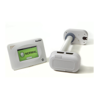
Room pressure can be measured using either a TSI through-the-wall sensor or a pressure
transducer.
TSI (Through-the-Wall) Sensor Calibration
NOTE: The TSI through-the-wall sensor is calibrated at the factory and does not normally need
adjustment when installed.
1. Select SENSOR SPAN item.
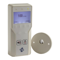
2. Position a thermal anemometer or other instrument configured to measure air velocity in the
door opening to obtain a velocity reading. Take a measurement of the air velocity
entering/exiting the door.
3. Input the reference measurement from step 3 into the PresSura controller.
4. Save the reading and exit the menu system.
Pressure Transducer Calibration
NOTE: This calibration process is to configure the PresSura controller to match the reading
from the pressure transducer. If the pressure transducer itself needs to be calibrated,
refer to the instructions that come with the pressure transducer.
1. Write down the output signal range and pressure range of the pressure transducer. As an
example for these instructions, we will assume the pressure transducer has an output signal
range of 0 to 10 V and a pressure range of -0.25 to +0.25 in. W.C.
2. Select the SENSOR MIN item and enter the minimum pressure range of the transducer. In
this example, you would enter -0.25 in. W.C.
3. Select the SENSOR MAX item and enter the maximum pressure range of the transducer. In
this example, you would enter +0.25 in. W.C.
 Loading...