
Do you have a question about the TSI Instruments PRESSURA RPC30 and is the answer not in the manual?
| Accuracy | +/- 0.25% of reading |
|---|---|
| Resolution | 0.001 in. H2O |
| Operating Temperature | 32 to 122°F (0 to 50°C) |
| Electrical Connection | Screw terminal block |
| Operating Humidity | 0 to 95% RH, non-condensing |
| Output Signal | 4-20 mA |
| Housing Material | Polycarbonate |
| Process Connection | 3/16 in. ID tubing |
| Storage Temperature | -40°C to 85°C |
| Power | 24 VDC ±10% |
| Power Supply | 24 VDC ±10% |
Details specific conditions and components excluded from the standard warranty coverage.
Outlines limits on express/implied warranties and disclaimers.
Defines buyer's remedy and sets limits on seller's liability for damages.
Explains TSI's commitment to prompt attention for instrument problems and service.
Lists registered and unregistered trademarks of TSI and other companies.
Provides instructions for safe and proper handling of the Model RPC30 Room Pressure Controller.
Explains the meaning and significance of the Caution symbol used in the manual.
Information on using access codes to manage system access and security.
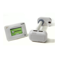
Overview of the PresSura RPC30 controller's purpose and basic operational principles.
Details of the operator panel, display, and keys for unit interaction and status monitoring.
Information on the USB port, visual, and audible alarm functions of the controller.
Details on alarm relay functions and guidance for contacting technical support.
Guide to programming the controller via its keypad and display, and understanding the menu system.
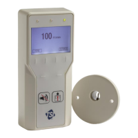
Procedures for calibrating sensors and maintaining the controller for optimal performance.
Steps to diagnose and resolve issues, and guidance for contacting technical support.
Technical specifications for the DIM, including display, range, resolution, and power requirements.
Details on inputs, dimensions, and weight for the velocity sensor components.
Technical information for Modbus communication protocol and its implementation.
Lists RAM variables, Modbus addresses, and RPC30 variable list for network communication.
Information on LonWorks objects and BACnet MS/TP object set for communication.
Wiring diagrams for various sensors and actuators used with the RPC30.
Details pin assignments, signal types, and descriptions for the main back panel connections.
Illustrations showing communication wiring for Modbus, BACnet, LONworks, and RS-485 loops.
Explains the two levels of passcode access for room mode and menu system operations.