13.12 Installation → Features
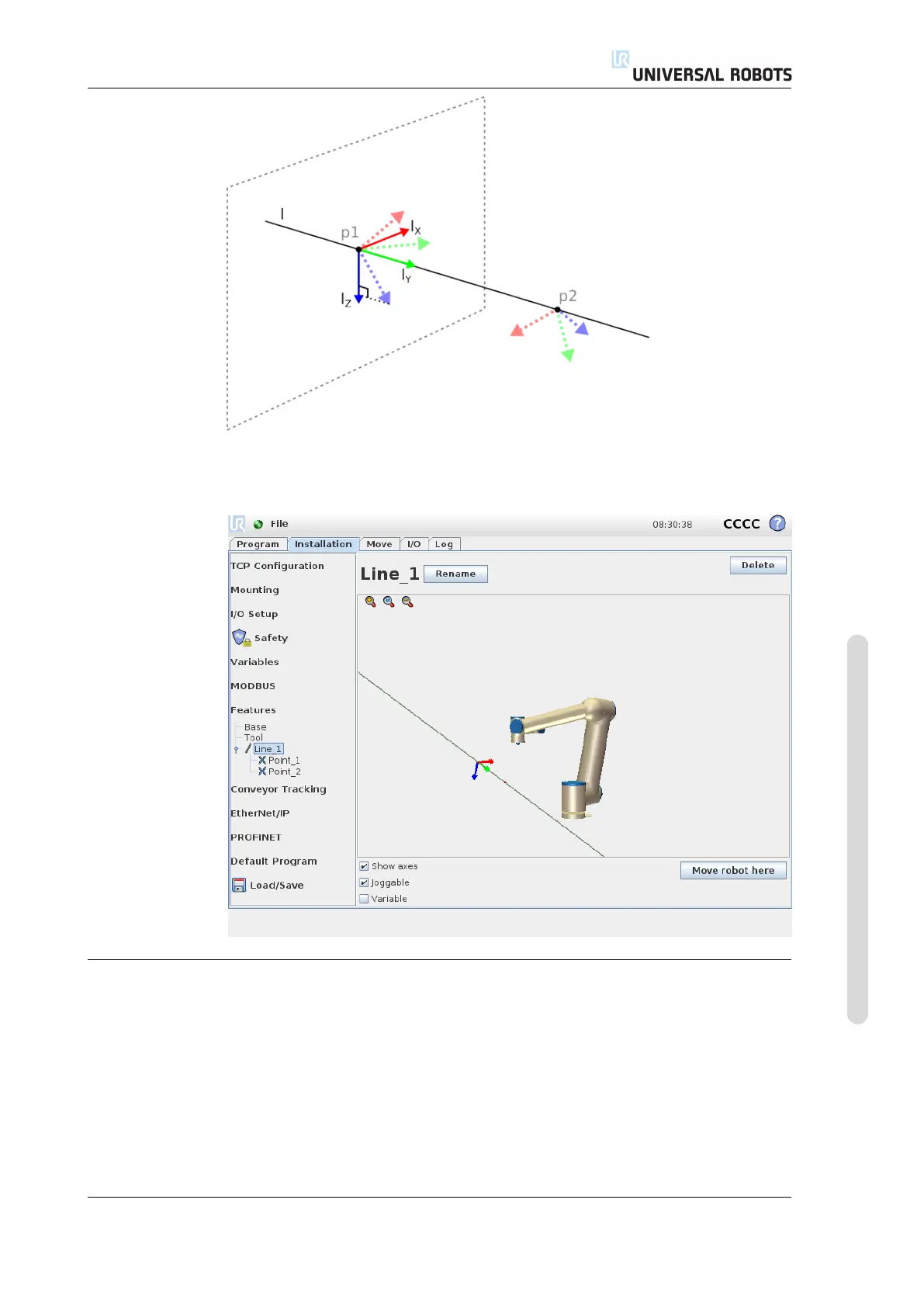
Figure 13.3: Definition of the line feature
13.12.4 New Plane
Push this button to add a plane feature to the installation. The plane feature is
typically chosen when there is a need for a frame with high precision, e.g. when
working with a vision system or doing movements relative to a table. A plane is
defined by three sub point features. The position of the coordinate system is the
same as the position for the first sub point. The z-axis is the plane normal, and the
y-axis is directed from the first point towards the second. The positive direction of
the z-axis is set so that the angle between the z-axis of the plane and the z-axis of
the first point is less than 180 degrees.
Version 3.4.5
Copyright © 2009–2017 by Universal Robots A/S. All rights reserved.
II-55 CB3

 Loading...


