19 Installing and uninstalling the interface
To achieve redundancy of the safety functionality, the controller box knows whether
it shall expect a EUROMAP 67 interface to be present or not. Therefore, the in-
stalling and uninstalling procedures below must be followed precisely.
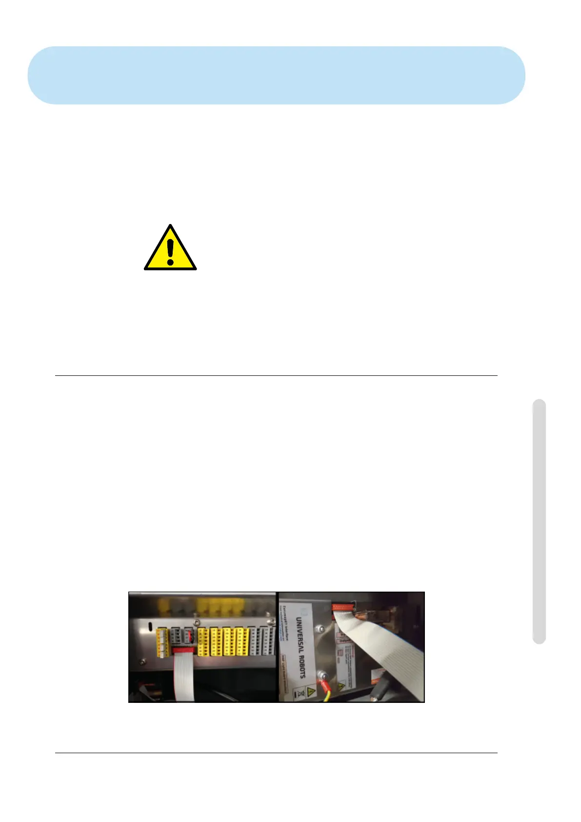
Please note the orientation of the ribbon cable below.
CAUTION:
1. Do not plug/unplug the ribbon cable when the controller box
is powered on.
2. The ground (earth) connection shall be screwed on when
plugging/unplugging the ribbon cable.
3. Never power on the control box without the ground (earth)
connection.
19.1 Installing
The interface can be placed at the bottom or in the left side of the controller box, see
pictures below and follow the procedure. It is not allowed to install the interface in
any other way.
1. Power down the controller box.
• The green light of the power button of the teach pendant must be off.
2. Mount the interface.
• Use 1 M6 nut to screw on the ground connector.
• Use 4 M4×8mm screws to screw on the interface.
• Use 4 M4×8mm screws to cover the empty holes.
• Click on the ribbon cable with the right orientation.
Figure 19.1: Ribbon cable connection
Version 3.4.5
Copyright © 2009–2017 by Universal Robots A/S. All rights reserved.
III-21 CB3

 Loading...


