14.29 Graphics Tab
the Conveyor Tracking defined in the installation is configured correctly, a linear or
circular conveyor can be tracked. The node can be added from the Wizard Pro-
gram node under the Structure tab. While the program is executing under the
Conveyor Tracking node, the robot will adjusts it’s movements to follow the
conveyor. Other movements are allowed while tracking the conveyor, but are rela-
tive to the motion of the conveyor belt.
14.28 Command: Suppress
Suppressed program lines are simply skipped when the program is run. A sup-
pressed line can be unsuppressed again at a later time. This is a quick way to make
changes to a program without destroying the original contents.
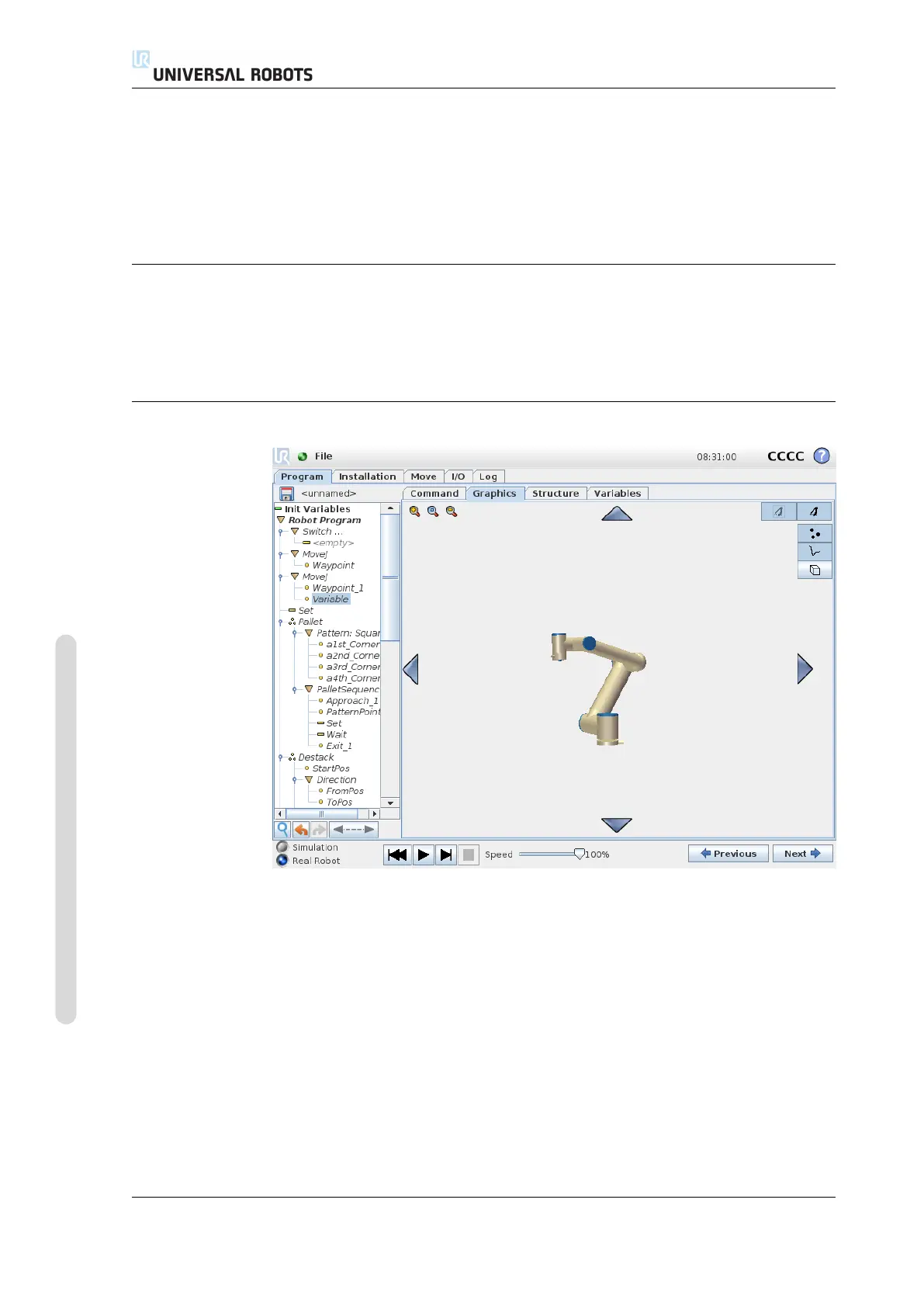
14.29 Graphics Tab
Graphical representation of the current robot program. The path of the TCP is
shown in the 3D view, with motion segments in black, and blend segments (transi-
tions between motion segments) shown in green. The green dots specify the posi-
tions of the TCP at each of the waypoints in the program. The 3D drawing of the
robot arm shows the current position of the robot arm, and the “shadow” of the
robot arm shows how the robot arm intends to reach the waypoint selected in the
left hand side of the screen.
If the current position of the robot TCP comes close to a safety or trigger plane, or
the orientation of robot tool is near the tool orientation boundary limit (see 10.12),
a 3D representation of the proximate boundary limit is shown. Note that when the
robot is running a program, the visualization of boundary limits will be disabled.
CB3 II-100 Version 3.4.5
Copyright © 2009–2017 by Universal Robots A/S. All rights reserved.

 Loading...


