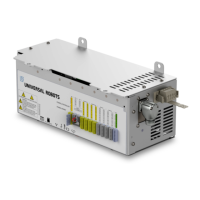
17.5 EUROMAP 12 to EUROMAP 67 conversion
1. Do you measure 24V between A9 and C9?
• The IMM must supply 24V to enable the I/O signals.
• If the robot and the IMM has common minus/0V then the robot 24V can
be used by connecting A9 to ZA9 and C9 to ZC9. IMM 24V is often present
at EUROMAP 12 pin 32.
2. Is the adaptor switching both robot emergency channels and both robot safety
devices channels?
• This is typically accomplished using 4 relays.
DANGER:
Make sure the E12 - E67 converter conforms to the EUROMAP 67
and EUROMAP 12 standards and that the safety functions are con-
structed with the correct performance level. Failure to follow this
warning could result in serious injury or death as the safety stop
function could be overridden.
Version 3.4.5
Copyright © 2009–2017 by Universal Robots A/S. All rights reserved.
III-9 CB3

 Loading...


