5.3 Controller I/O
• Use the same gnd (0V) for equipment and control box. The analog I/O is not
galvanically isolated from the control box.
• Use a shielded cable or twisted pairs. Connect the shield to the “GND” termi-
nal at the terminal called “Power”.
• Use of equipment that works in current mode. Current signals are less sensi-
tive to interferences.
Input modes can be selected in the GUI, see part II. The electrical specifications are
shown below.
Terminals Parameter Min Typ Max Unit
Analog input in current mode
[AIx - AG] Current 4 - 20 mA
[AIx - AG] Resistance - 20 - ohm
[AIx - AG] Resolution - 12 - bit
Analog input in voltage mode
[AIx - AG] Voltage 0 - 10 V
[AIx - AG] Resistance - 10 - Kohm
[AIx - AG] Resolution - 12 - bit
Analog output in current mode
[AOx - AG] Current 4 - 20 mA
[AOx - AG] Voltage 0 - 10 V
[AOx - AG] Resolution - 12 - bit
Analog output in voltage mode
[AOx - AG] Voltage 0 - 10 V
[AOx - AG] Current -20 - 20 mA
[AOx - AG] Resistance - 1 - ohm
[AOx - AG] Resolution - 12 - bit
The following examples show how to use the analog I/O.
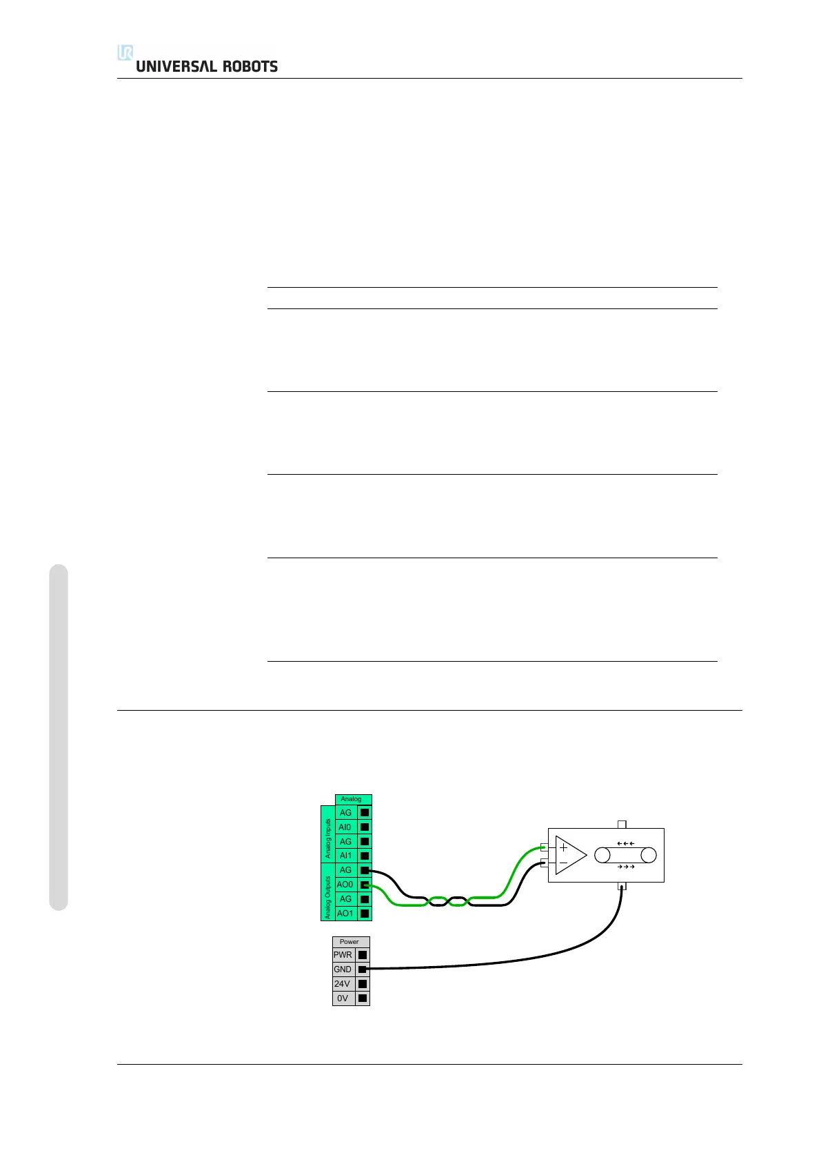
5.3.6.1 Using an analog output
Below is an example of how to control a conveyor belt with an analog speed control
input.
AG
AI1
AG
AO0
AG
AO1
AG
AI0
Analog
Analog Outputs
Analog Inputs
24V
0V
PWR
GND
Power
UR5/CB3 I-36 Version 3.4.5
Copyright © 2009–2017 by Universal Robots A/S. All rights reserved.

 Loading...


