3-64 OM 28Z3 US – Edition 2.0 * * 28Z3b340.fm
Operation
Re-equipping
Warning!
Re-equipping attachments –
Danger of personal injury!
☞ Observe the following instructions:
• Stop the engine.
• Fold the control lever base up.
• Re-equip attachments only with suitable tools.
• Do not align components with your fingers or your hands but use suita-
ble tools – danger of crushing!
☞ Once you have re-equipped the attachments, or before starting work, make
sure the attachment is safely locked with the stick and the tilt rod, or with
the Powertilt unit (option).
☞ Release the pressure – see chapter 3.28 Releasing the pressure on the
work hydraulics on page 3-56.
☞ Follow the safety instructions .
– see chapter 3.29 Coupling and uncoupling attachments on page 3-57.
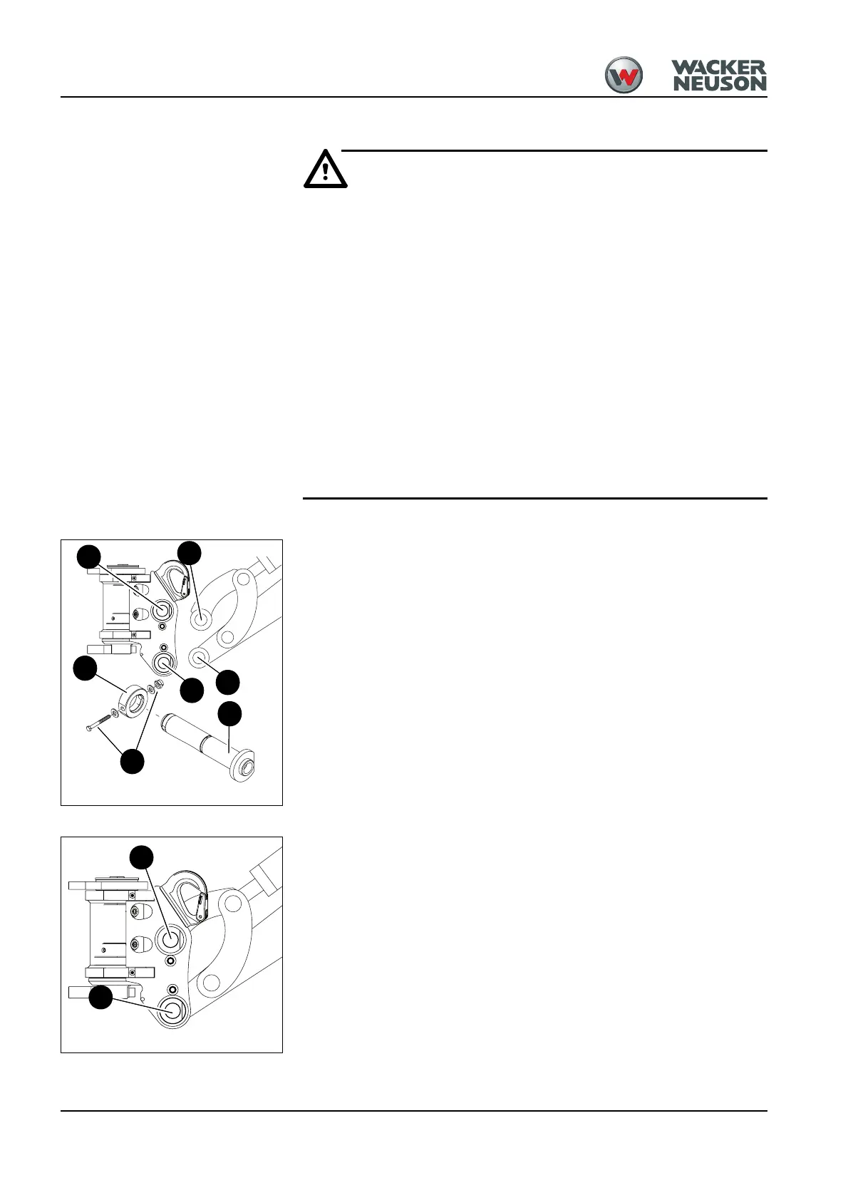
Mounting the Powertilt unit
Proceed as follows:
☞ Lower the Powertilt unit to the ground with its flat side facing down.
☞ Grease the joints and the pins before inserting them.
☞ Start the engine.
☞ Straighten the stick so that bores D and E are flush.
☞ Insert greased pin F.
☞ Mount ring J and tighten the securing elements G.
☞ Actuate the stick cylinder until bores H and I are flush.
☞ Insert greased pin F.
☞ Mount ring J and tighten the securing elements G.
Removing the Powertilt unit
Re-equip as follows:
☞ Lower the Powertilt unit to the ground with its flat side facing down.
☞ Stop the engine.
☞ Fold the control lever base up.
☞ Remove the ring and the securing elements.
☞ First remove pin A, and then pin B. Carefully expel pins that are stuck with a hammer
and a brass punch.
If pin A is stuck:
☞ Start the engine.
☞ Slighty raise and lower the boom to take the load off the pin.
☞ Stop the engine.
☞ Fold the control lever base up.
Fig. 85: Fitting the wheels
D
F
E
H
I
G
J
Fig. 86: Removing
A
B

 Loading...