OM 28Z3 US – Edition 2.0 * 28Z3b610.fm 6-3
Specifications
6.7 Electric system
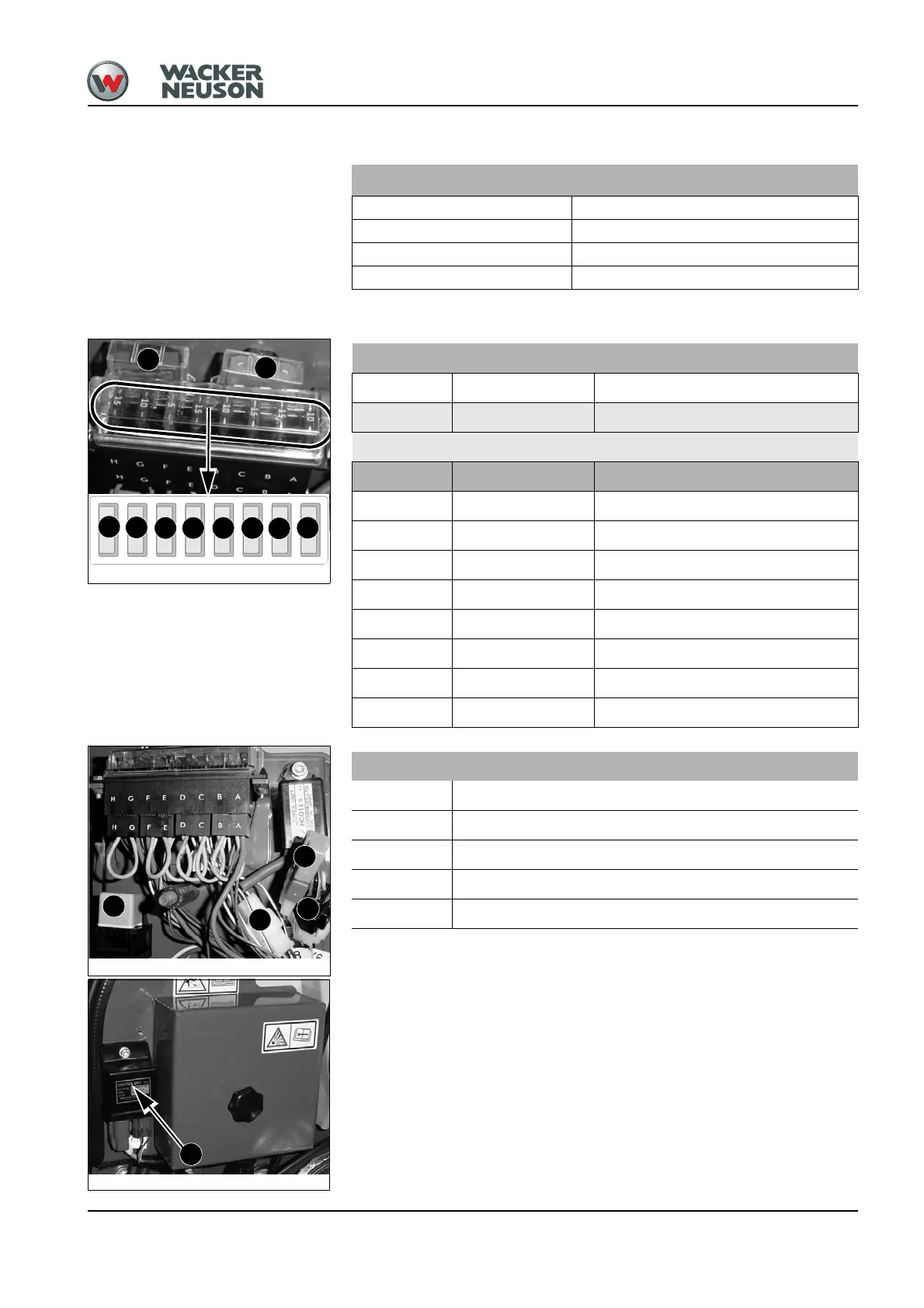
Fuse box in engine compartment
Electric system
Alternator 12 V 40 A
Starter 12 V 1.1 kW
Battery 12 V 43 Ah
Socket E.g. for 12V power outlet; 15 A max.
Fig. 138: Fuse box
F10
F9
F5
F4
F3
F8 F7 F6
F1
F2
Fuse no. Rated current (A) Protected circuit
F1 40 A – Start, preheat, cutoff solenoid
F2 50 A – Ignition lock
Fuse no. Rated current (A) Protected circuit
F3 10 A – Indicator, cutoff solenoid, relays
F4 15 A – Boom working light, heating
F5 15 A – Valves, horn
F6 10 A – Cab working light
F7 15 A – Wiper, interior light
F8 5 A – Proportional controls
F9 10 A – Rotating beacon, radio
F10 15 A – Socket, 12V power outlet
Fig. 139: Fuse box
K6
K8
K9
V1
Relay no. Protected circuit
V1 – Blocking diode
K6 – Preheating time lag relay (blue)
K7 – Starting relay
K8 – Preheating time lag relay (brown)
K9 – Pick-up contact cutoff solenoid relay
Fig. 140: Starting relay
K7

 Loading...