3-11
Phaser 3635MFP
IQ7
Image Quality
Draft 4
IQ7 Light Image RAP
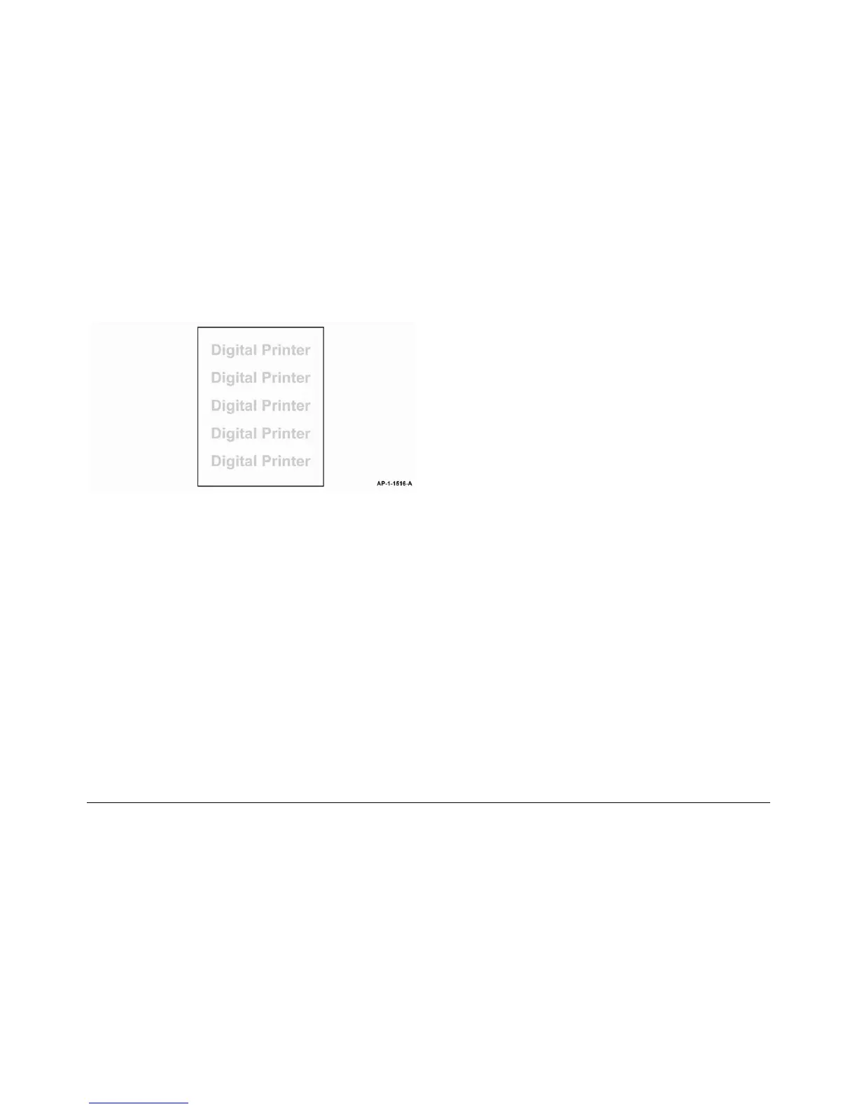
Use this RAP when the machine produces light images in all modes, as shown in Figure 1.
Figure 1 Light image
Procedure
WARNING
Switch off the electricity to the machine. Disconnect the power cord from the customer
supply while performing tasks that do not need electricity. Electricity can cause death or
injury. Moving parts can cause injury.
NOTE: For solid print area specifications, refer to IQS 1 Solid Area Density.
Perform the following:
1. If the fault appears only in copy mode when using the DADF, check that the scanner lock,
PL 14.10 Item 22 is completely unlocked.
2. Ensure that the paper tray settings match the paper or media size in the trays.
3. Examine the print cartridge, PL 9.10 Item 1. Ensure that it is free from all packing or seal-
ing material.
4. Perform the Shading Test procedure, GP 15. If the shading test fails:
a. Install new components as necessary:
• CCD module, PL 14.10 Item 8.
• CCD module cable, PL 14.10 Item 23.
• Scanner assembly, PL 14.10 Item 26.
• Main PWB, PL 3.10 Item 6.
b. Perform OF7 Main PWB Check RAP.
5. Remove the LSU, PL 6.10 Item 1. Clean the LSU window using a clean, lint-free cloth. If
necessary, install a new LSU, PL 6.10 Item 1.
6. Refer to Wiring Diagram 2. Perform the following:
• Check the spring contacts between the HVPS PL 1.10 Item 3 and the print cartridge
PL 9.10 Item 1. The spring contacts supply the voltages to the print cartridge. If nec-
essary, clean the spring contacts.
• If necessary, install a new HVPS, PL 1.10 Item 3.
7. Refer to Wiring Diagram 2. Check the wiring between CN5 on the HVPS and CN31 on the
Main PWB.
8. Check the spring contact from the HVPS to the transfer roll, PL 9.10 Item 2. If necessary,
clean the spring contact. Install new components as necessary, PL 9.10.
9. Refer to Wiring Diagram 5. Check the wiring between the 3 thermistors and CN16 on the
Main PWB. Light copies can be caused by a faulty thermistor. Install new components as
necessary:
• Thermistor 1, 2 or 3 PL 10.25 Item 5.
10. Install new components as necessary:
• HVPS, PL 1.10 Item 3.
• Print cartridge, PL 9.10 Item 1.
 Loading...