4-24
Phaser 3635MFP
REP 7.3, REP 7.4
Draft 4
Repairs and Adjustments
REP 7.3 Bypass Pickup Roll
Parts List on PL 7.10
Removal
WARNING
Switch off the electricity to the machine. Disconnect the power cord from the customer
supply while performing tasks that do not need electricity. Electricity can cause death or
injury. Moving parts can cause injury.
CAUTION
Before performing this procedure, refer to General Disassembly Precautions, GP 10.
1. Open the front cover assembly, PL 28.10 Item 7.
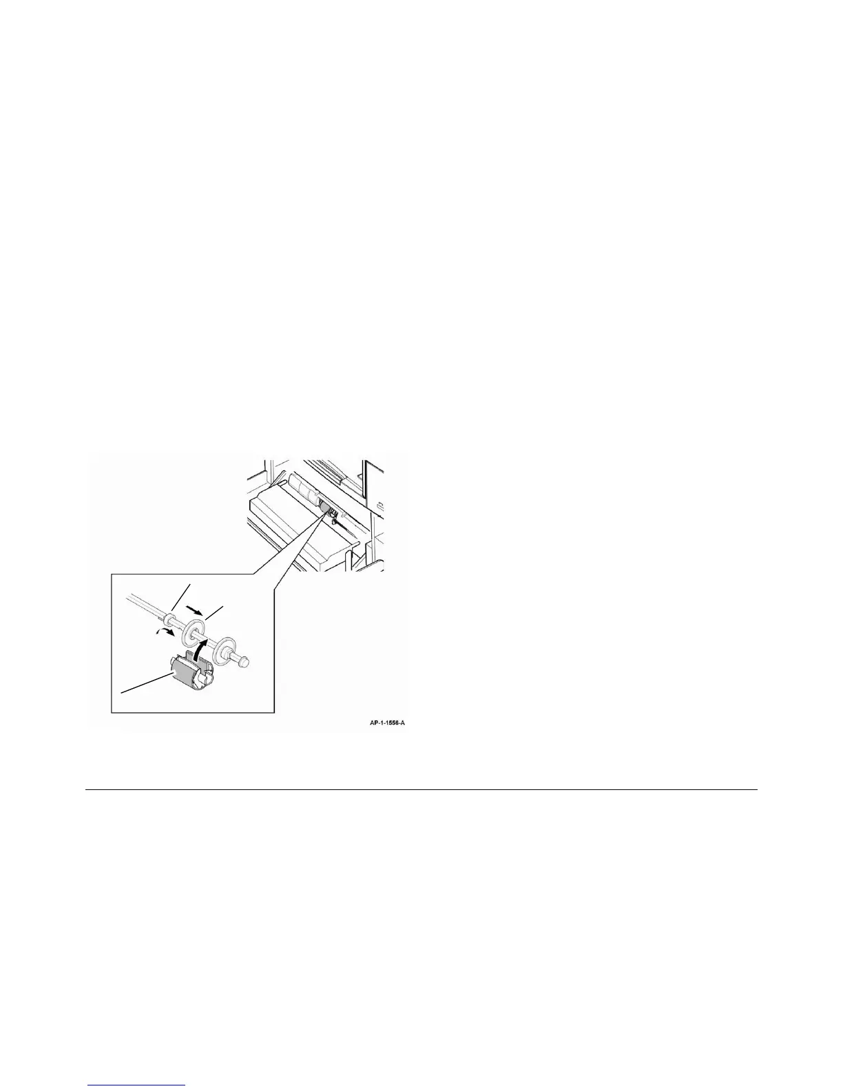
2. Remove the bypass pickup roll, refer to Figure 1. Perform the following:
a. Release the tab, then slide the locking collar to the left.
b. Move the pickup roll and the left idler to the left.
c. Rotate the pickup roll through 90 degrees to remove it from the shaft.
Figure 1 Pickup roll removal
Replacement
1. Replacement is the reverse of the removal procedure.
REP 7.4 Tray 2 Feed Motor and Pickup Solenoid
Parts List on PL 8.17
Removal
WARNING
Switch off the electricity to the machine. Disconnect the power cord from the customer
supply while performing tasks that do not need electricity. Electricity can cause death or
injury. Moving parts can cause injury.
WARNING
Take care during this procedure. Sharp edges may be present that can cause injury.
CAUTION
Before performing this procedure, refer to General Disassembly Precautions, GP 10.
1. Remove the tray 2 module, PL 8.15 Item 28.
2. Remove 3 screws to release the tray 2 left cover, PL 8.15 Item 5.
CAUTION
Take care when releasing the tabs at the corners, they may be susceptible to breaking.
3. Use a flat bladed screwdriver to release the tabs underneath and then lift the panel off the
pegs at the top.
4. Remove the drive assembly bracket, PL 8.15 Item 20.
5. Remove the tray 2 feed motor, PL 8.15 Item 23 or tray 2 pickup solenoid, PL 8.17 Item 24
as required.
Replacement
WARNING
Ensure all ground leads are connected.
1. Replacement is the reverse of the removal procedure.
NOTE: When reinstalling the side panel, stand the tray on the rear panel and engage the
lower tabs before snapping the top edge over the pegs.
Locking collar
Pickup roll
Left idler
 Loading...