4-11
Phaser 3635MFP
REP 4.1
Repairs and Adjustments
Draft 4
REP 4.1 Main BLDC Motor
Parts List on PL 4.10
Removal
WARNING
Switch off the electricity to the machine. Disconnect the power cord from the customer
supply while performing tasks that do not need electricity. Electricity can cause death or
injury. Moving parts can cause injury.
WARNING
Take care during this procedure. Sharp edges may be present that can cause injury.
CAUTION
Before performing this procedure, refer to General Disassembly Precautions, GP 10.
1. Remove the left cover, REP 28.1.
CAUTION
Take care to identify the connections to the Main PWB. The 4 pin connections are interchang-
able.
• CN4, 4 wires: 3 grey, 1 black.
• CN5, 3 wires: 2 grey, 1 black.
• CN17, 4 wires: 3 grey, 1 black.
• CN18, not used.
• CN38, 4 wires: 2 grey 2 black.
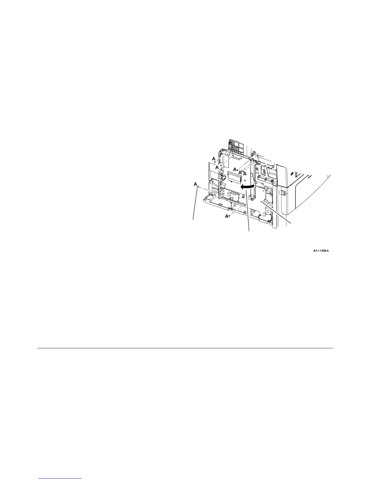
2. Reposition the main PWB assembly to allow access the main drive assembly, Figure 1.
NOTE: Disconnect harnesses as required to allow access to the main drive assembly.
Figure 1 Main drive assembly access
3. Remove 5 screws numbered 1 to 5, then remove the main drive assembly, PL 3.10 Item
1.
4. Remove 4 screws, then remove the main BLDC motor from the assembly, PL 4.10 Item 1.
Replacement
1. Install the main BLDC motor, PL 4.10 Item 1 to the main drive assembly using 4 screws.
2. Install 5 screws numbered 1 to 5 to install the main drive assembly, refer to Figure 1.
3. Reinstall the main PWB assembly.
4. Replacement is the reverse of the removal procedure.
2
Move the main PWB to access the
main drive assembly.
1
Remove 7 screws marked A.
Main drive assembly
 Loading...