4-5
Phaser 3635MFP
REP 2.1
Repairs and Adjustments
Draft 4
REP 2.1 User Interface Assembly
Parts List on PL 2.10
Removal
WARNING
Switch off the electricity to the machine. Disconnect the power cord from the customer
supply while performing tasks that do not need electricity. Electricity can cause death or
injury. Moving parts can cause injury.
CAUTION
Before performing this procedure, refer to General Disassembly Precautions, GP 10.
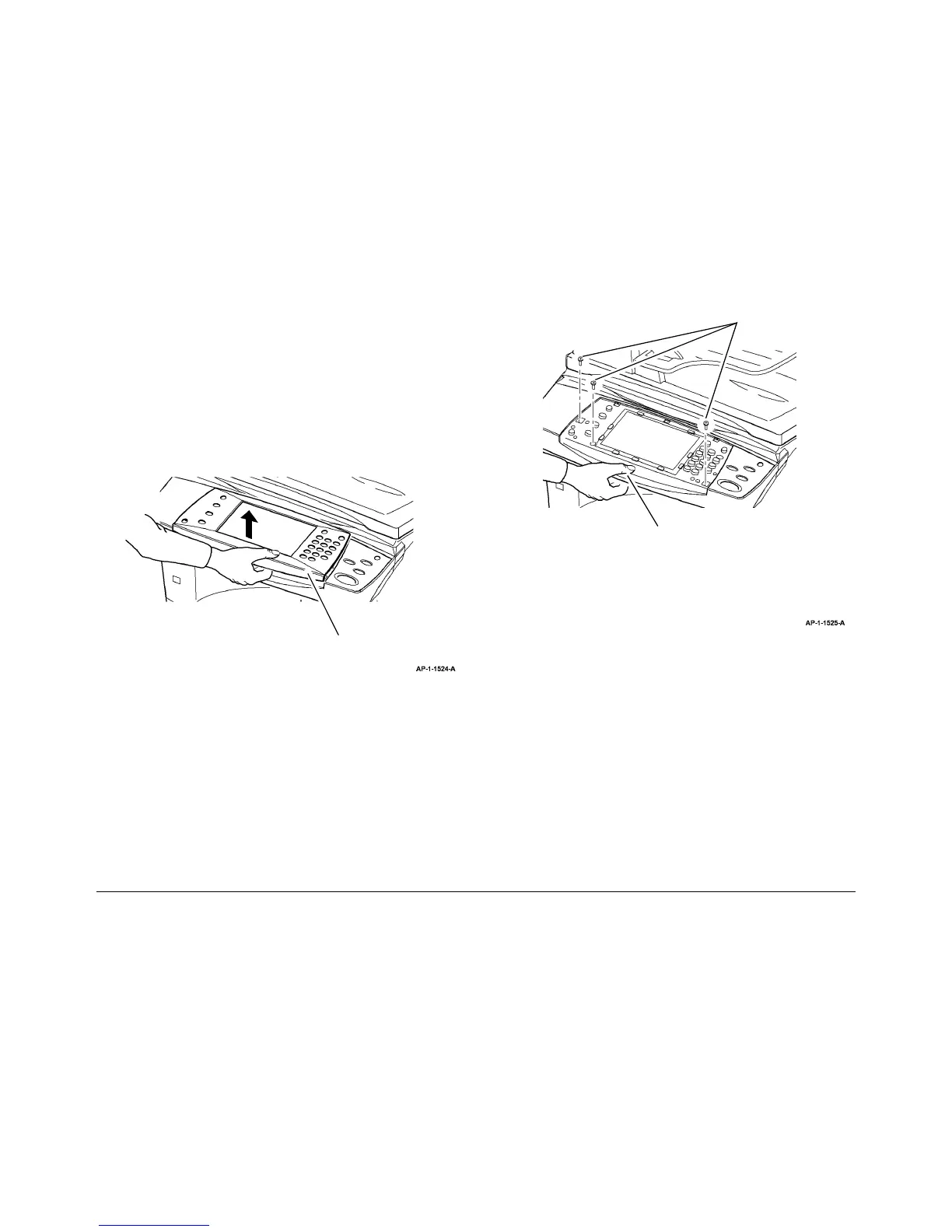
1. Remove the UI inlay, Figure 1.
Figure 1 UI inlay removal
CAUTION
Take care to identify the connections to the UI PWB. The 3 pin connections are interchange-
able.
• CN2, 3 wires: 1 black, 1 white, 1 red.
• CN11, 4 wires: 1 black, 3 gray.
2. Remove the UI panel assembly, Figure 2.
Figure 2 UI assembly removal
Replacement
1. Replacement is the reverse of the removal procedure.
1
Carefully lift off the UI inlay.
Remove 3 screws.
2
Release the clip underneath the UI
assembly, then lift off the UI assembly.
3
Disconnect CN1, CN2 and CN11 from
the UI PWB.
 Loading...