202 www.xilinx.com 7 Series FPGAs GTP Transceivers User Guide
UG482 (v1.9) December 19, 2016
Chapter 4: Receiver
Using RX Channel Bonding
The user must follow the steps described below to use the receiver’s channel bonding feature.
Enabling Channel Bonding
Each GTP transceiver includes a circuit that performs channel bonding by controlling the pointers of
the RX elastic buffer. Because channel bonding requires the use of the RX buffer, the RXBUF_EN
attribute must be set to TRUE.
Each GTP transceiver has a channel bonding circuit. Configuring a GTP transceiver for channel
bonding requires these steps:
1. Set the channel bonding mode for each GTP transceiver.
2. Tie the RXCHBONDMASTER of the master transceiver High.
3. Tie the RXCHBONDSLAVE of the slave transceiver(s) High.
4. Connect the channel bonding port from the master to each slave, either directly or by daisy
chaining.
5. Set the channel bonding sequence and detection parameters.
Channel Bonding Mode
The channel bonding mode for each GTP transceiver determines whether channel bonding is active
and whether the GTP transceiver is the master or a slave. Each set of channel bonded GTP
transceivers must have one master and any number of slaves. To turn on channel bonding for a group
of GTP transceivers, one transceiver is set to master. The remaining GTP transceivers in the group
are set to slaves.
Connecting Channel Bonding Ports
The channel bonding operation requires connecting the master GTP transceiver RXCHBONDO
port to the RXCHBONDI port of all slaves in the group. Only GTP transceivers belonging to the
same column can be channel bonded together. A direct connection is required for adjacent GTP
transceivers. To directly connect a master to a slave:
1. Connect the RXCHBONDO port of the master to the RXCHBONDI port of the slave.
2. Tie the RXCHBONDMASTER of the master transceiver High.
3. Tie the RXCHBONDSLAVE of each slave transceiver High.
When GTP transceivers are directly connected, meeting the timing constraints becomes difficult as
the transceivers get further apart. The solution to this problem is to connect the transceivers in a
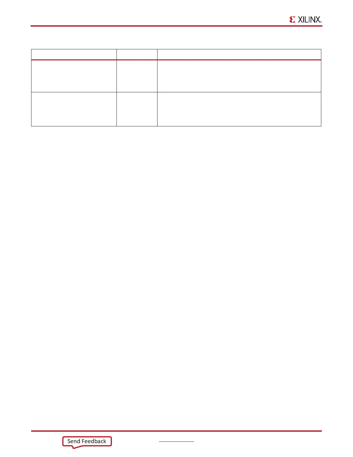
RX_DATA_WIDTH Integer Sets the bit width of the RXDATA port. When 8B/10B encoding is
enabled, RX_DATA_WIDTH must be set to 20 or 40. Valid settings are
16, 20, 32, and 40.
See Interface Width Configuration, page 214 for more details.
RX_DISPERR_SEQ_MATCH String Specifies whether the disparity error status of a decoded byte must match
the indicator in the channel bonding and clock correction sequence.
TRUE: The disparity error must be matched.
FALSE: The disparity error status is ignored.
Table 4-40: RX Channel Bonding Attributes (Cont’d)
Attribute Type Description

 Loading...


