106 www.xilinx.com 7 Series FPGAs GTP Transceivers User Guide
UG482 (v1.9) December 19, 2016
Chapter 3: Transmitter
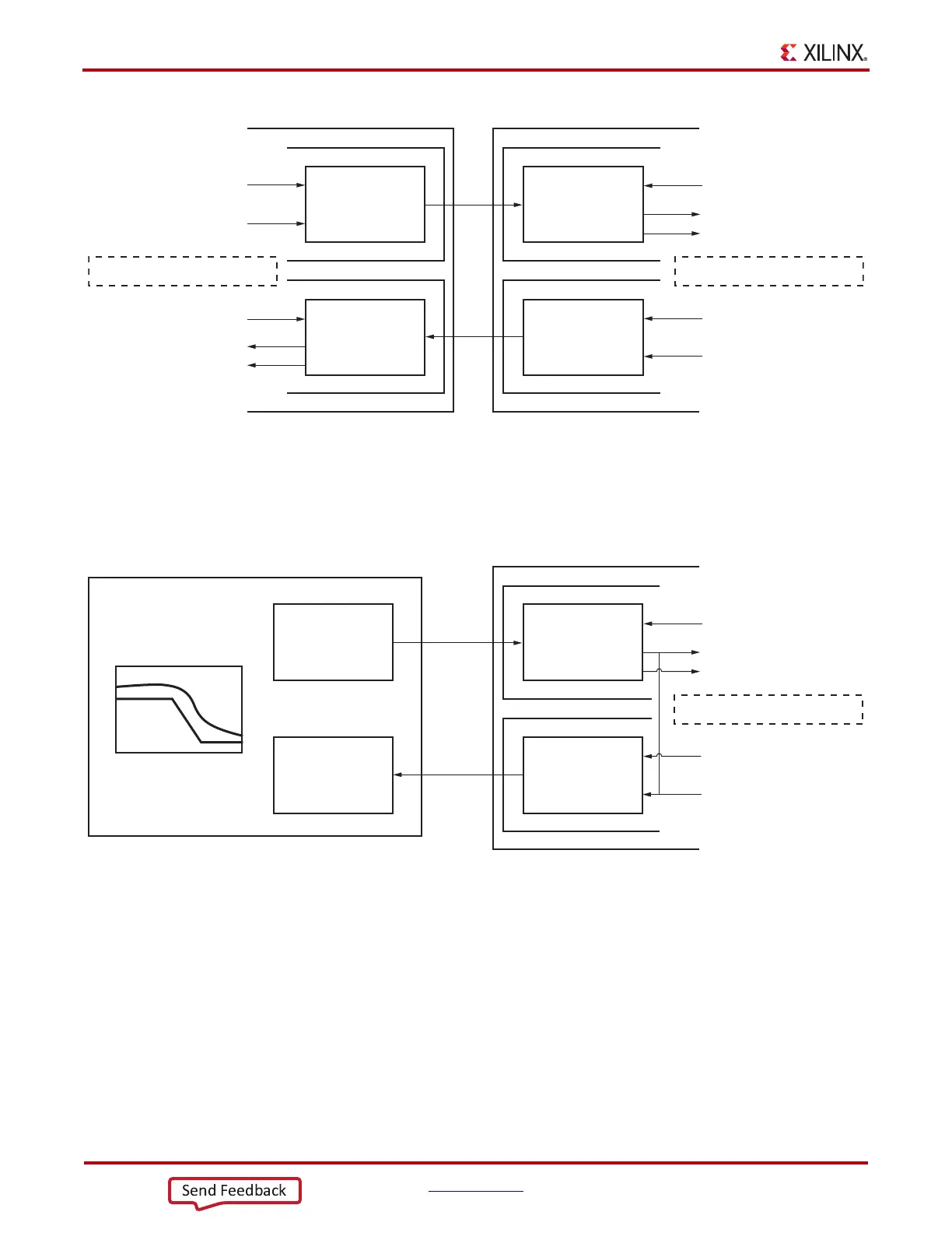
To calculate accurately the receiver’s bit error rate (BER), an external jitter tolerance tester should
be used. For the test, the GTP transceiver should loop the received error status back through the
transmitter by setting RXPRBS_ERR_LOOPBACK to 1 (Figure 3-19). The same setting should be
applied to RXPRBSSEL and TXPRBSSEL.
TX Polarity Control
Functional Description
If TXP and TXN differential traces are accidentally swapped on the PCB, the differential data
transmitted by the GTP transceiver TX is reversed. One solution is to invert the parallel data before
serialization and transmission to offset the reversed polarity on the differential pair. The TX polarity
control can be accessed through the TXPOLARITY input from the fabric user interface. It is driven
High to invert the polarity of outgoing data.
X-Ref Target - Figure 3-18
Figure 3-18: Link Test Mode with a PRBS-7 Pattern
001
001
001
001
TXPRBSSEL
TX Pattern
Generator
TX Pattern
Generator
RX Pattern
Checker
RX Pattern
Checker
TXPRBSFORCEERR
RXPRBSSEL
RXPRBS_ERR_LOOPBACK =0
RXPRBSERR
RX_PRBS_ERR_CNT
RXPRBSSEL
RXPRBSERR
RX_PRBS_ERR_CNT
RXPRBS_ERR_LOOPBACK =0
TXPRBSSEL
TXPRBSFORCEERR
UG482_c3_17_110911
X-Ref Target - Figure 3-19
Figure 3-19: Jitter Tolerance Test Mode with a PRBS-7 Pattern
Jitter Tester
001
001
TX
PRBS-7 pattern
with jitter
TX Pattern
Generator
RX
Pattern
Checker
RX Pattern
Checker
RXPRBSSEL
RXPRBSERR
RX_PRBS_ERR_CNT
RXPRBS_ERR_LOOPBACK =1
TXPRBSSEL
TXPRBSFORCEERR
UG482_c3_18_110911

 Loading...


