160 www.xilinx.com 7 Series FPGAs GTP Transceivers User Guide
UG482 (v1.9) December 19, 2016
Chapter 4: Receiver
inverted by controlling RXPOLARITY. Otherwise, the PRBS checker does not lock. When it finds
the pattern, it can detect PRBS errors by comparing the incoming pattern with the expected pattern.
The expected pattern is generated from the previous incoming data. The checker counts the number
of word (20 bits per word) errors and increments the word error counter by 1 when an error(s) is
found in the incoming parallel data. Thus the word error counter might not match the actual number
of bit errors if the incoming parallel data contains two or more bit errors. The error counter stops
counting when reaching 0xFFFF.
When the error occurs, RXPRBSERR is asserted. When no error is found in the following incoming
data, RXPRBSERR is cleared. Asserting RXPRBSCNTRESET clears the error counter.
GTRXRESET and RXPCSRESET also reset the count.
Refer to TX Pattern Generator, page 103 for more information about use models.
RX Byte and Word Alignment
Functional Description
Serial data must be aligned to symbol boundaries before it can be used as parallel data. To make
alignment possible, transmitters send a recognizable sequence, usually called a comma. The
receiver searches for the comma in the incoming data. When it finds a comma, it moves the comma
to a byte boundary so the received parallel words match the transmitted parallel words.
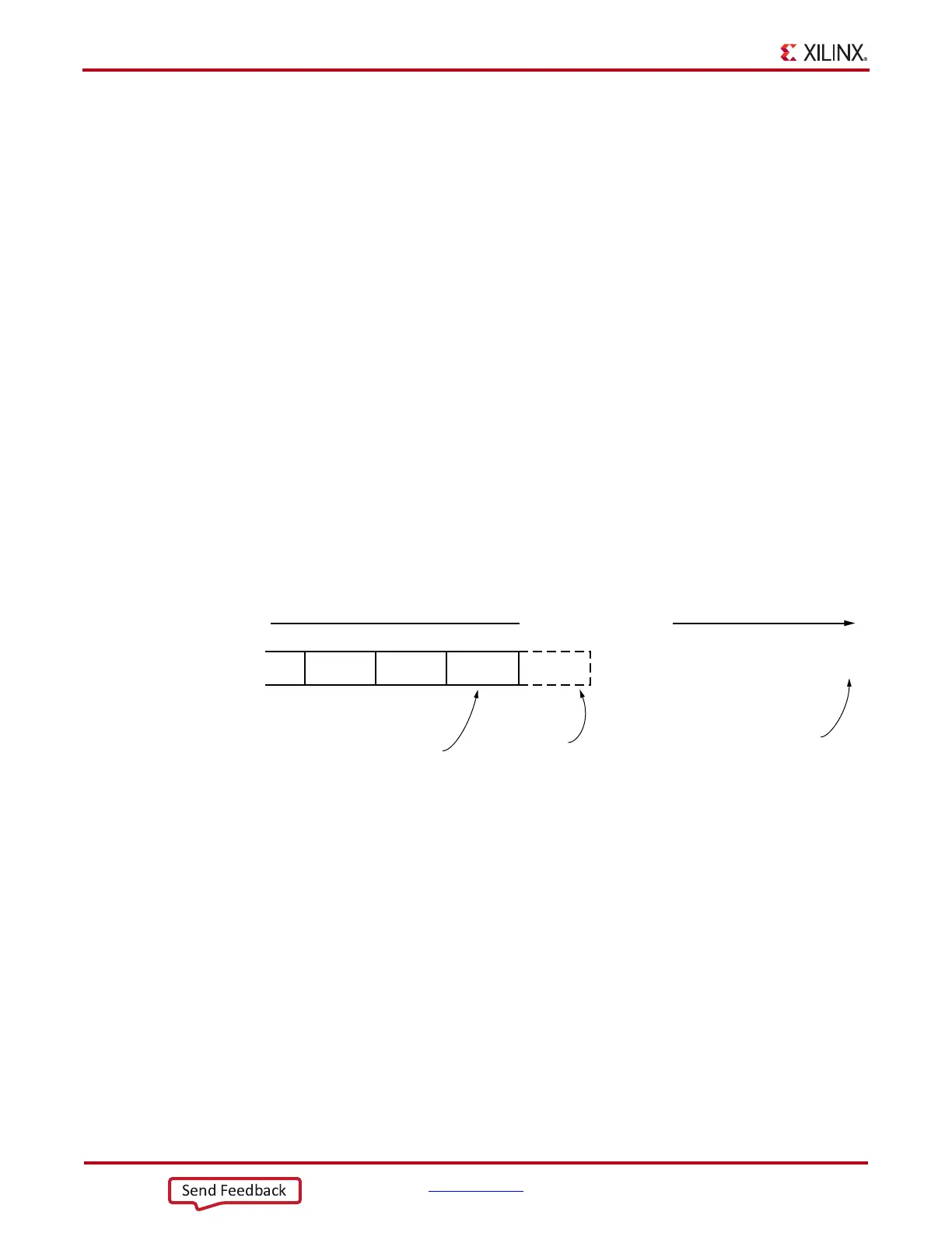
Figure 4-25 shows the alignment to a 10-bit comma. The RX receiving unaligned bits are on the
right side. The serial data with the comma is highlighted in the middle. Byte aligned RX parallel data
is on the left.
X-Ref Target - Figure 4-25
Figure 4-25: Conceptual View of Comma Alignment (Aligning to a 10-Bit Comma)
1001011000010010011010111001100111001011111001011011001010100100010101010101100110
All Subsequent Data
Aligned to Correct
Byte Boundary
Alignment Block
Finds Comma
Transmitted First
UG482_c4_14_110911
Stream of Serial Data

 Loading...


