38 www.xilinx.com 7 Series FPGAs GTP Transceivers User Guide
UG482 (v1.9) December 19, 2016
Chapter 2: Shared Features
Reset and Initialization
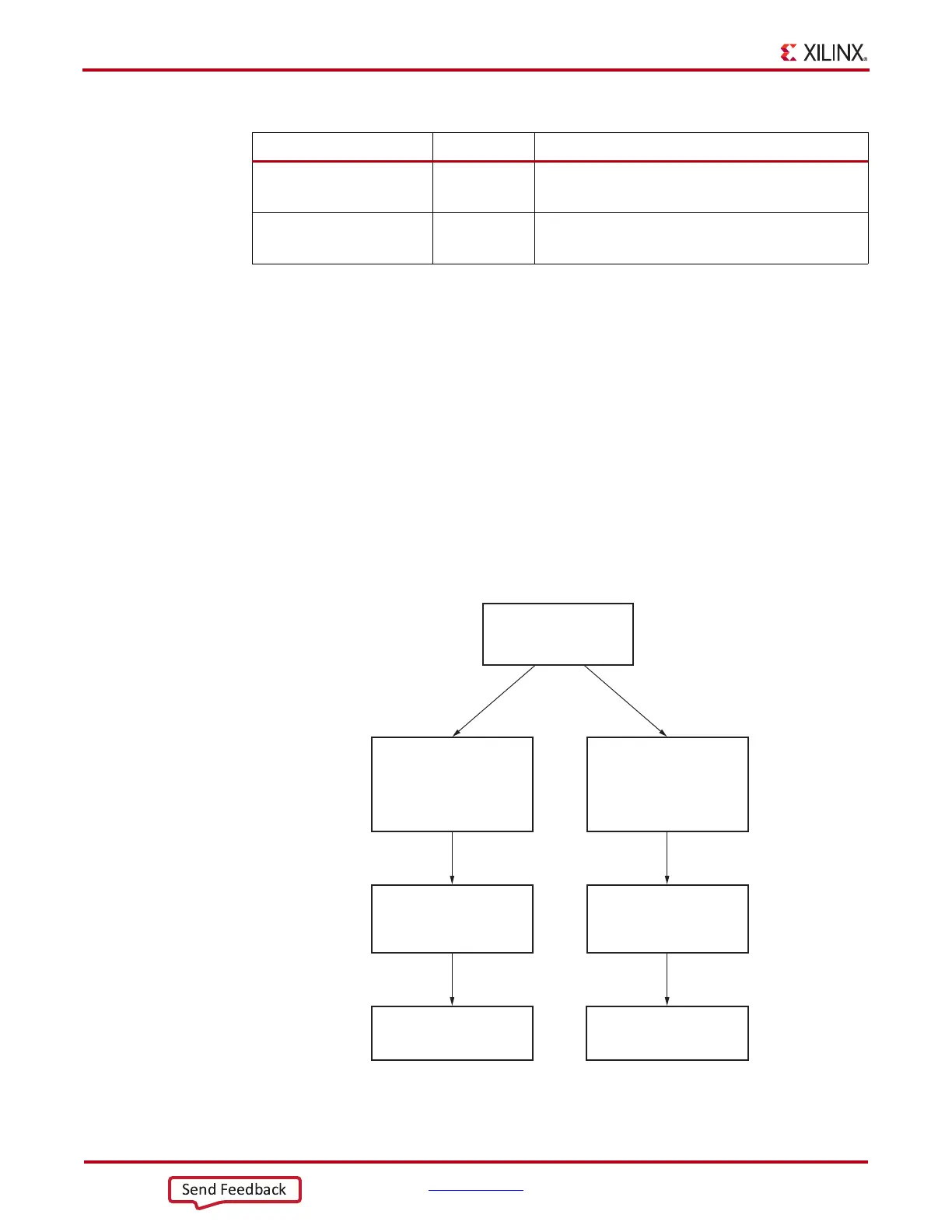
The GTP transceiver must be initialized after FPGA device power-up and configuration before it
can be used. The GTP transceiver’s transmitter (TX) and receiver (RX) can be initialized
independently and in parallel as shown in Figure 2-11. The GTP transceiver’s TX and RX
initialization comprises two steps:
1. Initializing the associated PLL driving TX/RX
2. Initializing the TX and RX datapaths (PMA + PCS)
The GTP transceiver’s TX and RX can receive a clock from either PLL0 or PLL1. The associated
PLL (PLL0 /PLL1) used by the TX and RX must be initialized first before TX and RX initialization.
Any PLL used by the TX and RX is reset individually and its reset operation is completely
independent from all TX and RX resets. The TX and RX datapaths must be initialized only after the
associated PLL is locked.
PLL0_INIT_CFG
PLL1_INIT_CFG
24-bit Hex
Reserved. The recommended value from the 7 Series
FPGAs Transceivers Wizard should be used.
PLL0_DMON_CFG
PLL1_DMON_CFG
1-bit Binary
Reserved. The recommended value from the 7 Series
FPGAs Transceivers Wizard should be used.
Table 2-9: PLL Attributes (Cont’d)
Attribute Type Description
X-Ref Target - Figure 2-11
Figure 2-11: GTP Transceiver Initialization Overview
After FPGA
Configuration
Initialize PLL
(PLL0/PLL1)
used by TX
TX Initialization By
GTTXRESET
TXRESETDONE RXRESETDONE
RX Initialization By
GTRXRESET
Initialize PLL
(PLL0/PLL1)
used by RX
UG482_c2_15_040412

 Loading...


