7 Series FPGAs GTP Transceivers User Guide www.xilinx.com 103
UG482 (v1.9) December 19, 2016
TX Pattern Generator
15. Deassert TXDLYEN for the master lane.
16. Assert TXPHINIT for all slave lane(s). Hold this signal High until the rising edge of
TXPHINITDONE of the respective slave lane is observed.
17. Deassert TXPHINIT for the slave lane in which the TXPHINITDONE is asserted.
18. When TXPHINIT for all slave lane(s) are deasserted, assert TXPHALIGN for all slave lane(s).
Hold this signal High until the rising edge of TXPHALIGNDONE of the respective slave lane
is observed.
19. Deassert TXPHALIGN for the slave lane in which the TXPHALIGNDONE is asserted.
20. When TXPHALIGN for all slave lane(s) are deasserted, assert TXDLYEN for the master lane.
This causes TXPHALIGNDONE of the master lane to be deasserted.
21. Wait until TXPHALIGNDONE of the master lane reasserts. Phase and delay alignment for the
multi-lane interface is complete. Continue to hold TXDLYEN for the master lane High to adjust
TXUSRCLK to compensate for temperature and voltage variations.
TX Pattern Generator
Functional Description
Pseudo-random bit sequences (PRBS) are commonly used to test the signal integrity of high-speed
links. These sequences appear random but have specific properties that can be used to measure the
quality of a link. The GTP transceiver pattern generator block can generate several
industry-standard PRBS patterns listed in Table 3-18.
In addition to PRBS patterns, the GTP transceiver supports 16-UI or 20-UI square wave test
patterns, depending on data width as well as a 2-UI square wave test pattern and PCI Express
compliance pattern generation (see Table 3-19 and Figure 3-16). Clocking patterns are usually used
to check PLL random jitter often done with a spectrum analyzer.
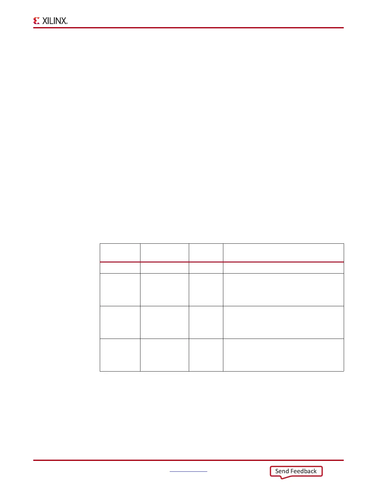
Table 3-18: Supported PRBS Patterns
Name Polynomial
Length of
Sequence
Description
PRBS-7 1 + X
6
+ X
7
2
7
- 1 bits Used to test channels with 8B/10B.
PRBS-15 1 + X
14
+ X
15
2
15
- 1 bits
ITU-T Recommendation O.150, Section 5.3.
PRBS-15 is often used for jitter measurement
because it is the longest pattern the Agilent
DCA-J sampling scope can handle.
PRBS-23 1 + X
18
+ X
23
2
23
- 1 bits
ITU-T Recommendation O.150, Section 5.6.
PRBS-23 is often used for non-8B/10B encoding
schemes. It is one of the recommended test
patterns in the SONET specification.
PRBS-31 1 + X
28
+ X
31
2
31
- 1 bits
ITU-T Recommendation O.150, Section 5.8.
PRBS-31 is often used for non-8B/10B encoding
schemes. It is a recommended PRBS test pattern
for 10 Gigabit Ethernet. See IEEE 802.3ae-2002.

 Loading...


