104 www.xilinx.com 7 Series FPGAs GTP Transceivers User Guide
UG482 (v1.9) December 19, 2016
Chapter 3: Transmitter
The error insertion function is supported to verify link connection and also for jitter tolerance tests.
When an inverted PRBS pattern is necessary, the TXPOLARITY signal is used to control polarity.
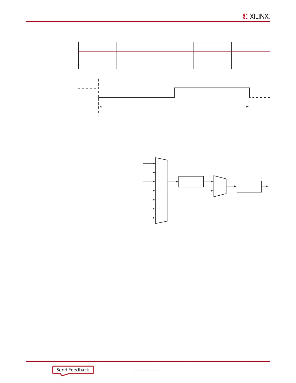
Figure 3-17 shows the TX pattern generator block.
Ports and Attributes
Table 3-20 defines the pattern generator ports.
Table 3-19: PCI Express Compliance Pattern
Symbol K28.5 D21.5 K28.5 D10.2
Disparity 0 1 1 0
Pattern 0011111010 1010101010 1100000101 0101010101
X-Ref Target - Figure 3-16
Figure 3-16: 20-UI Square Wave
X-Ref Target - Figure 3-17
Figure 3-17: TX Pattern Generator Block
PRBS-7
Error
Insertions
Polarity
Inversion
PRBS-15
PRBS-23
PRBS-31
PCI Express Compliance Pattern
Square Wave with 2 UI period
Square Wave with
16 UI or 20 UI period
TXDATA
UG482_c3_16_110911

 Loading...


