7 Series FPGAs GTP Transceivers User Guide www.xilinx.com 213
UG482 (v1.9) December 19, 2016
FPGA RX Interface
FPGA RX Interface
Functional Description
The FPGA RX interface is the FPGA’s gateway to the RX datapath of the GTP transceiver.
Applications receive data through the GTP transceiver by reading data from the RXDATA port on
the positive edge of RXUSRCLK2. The width of the port can be configured to be two or four bytes
wide. The actual width of the port depends on the RX_DATA_WIDTH attribute and RX8B10BEN
port setting. Port widths can be 16, 20, 32, and 40 bits. The rate of the parallel clock (RXUSRCLK2)
at the interface is determined by the RX line rate, the width of the RXDATA port, and whether or not
8B/10B decoding is enabled. In some operating modes, a second parallel clock (RXUSRCLK) must
be provided for the internal PCS logic in the transmitter. This section shows how to drive the parallel
clocks and explains the constraints on those clocks for correct operation.
Interface Width Configuration
The 7 series GTP transceiver contains a 2-byte internal datapath. The FPGA interface width is
configurable by setting the RX_DATA_WIDTH attribute. When the 8B/10B decoder is enabled,
RX_DATA_WIDTH must be configured to 20 bits or 40 bits, and in this case, the FPGA RX
interface only uses the RXDATA port. For example, RXDATA[15:0] is used when the FPGA
interface width is 16. When the 8B/10B decoder is bypassed, RX_DATA_WIDTH can be
configured to any of the available widths: 16, 20, 32, or 40 bits.
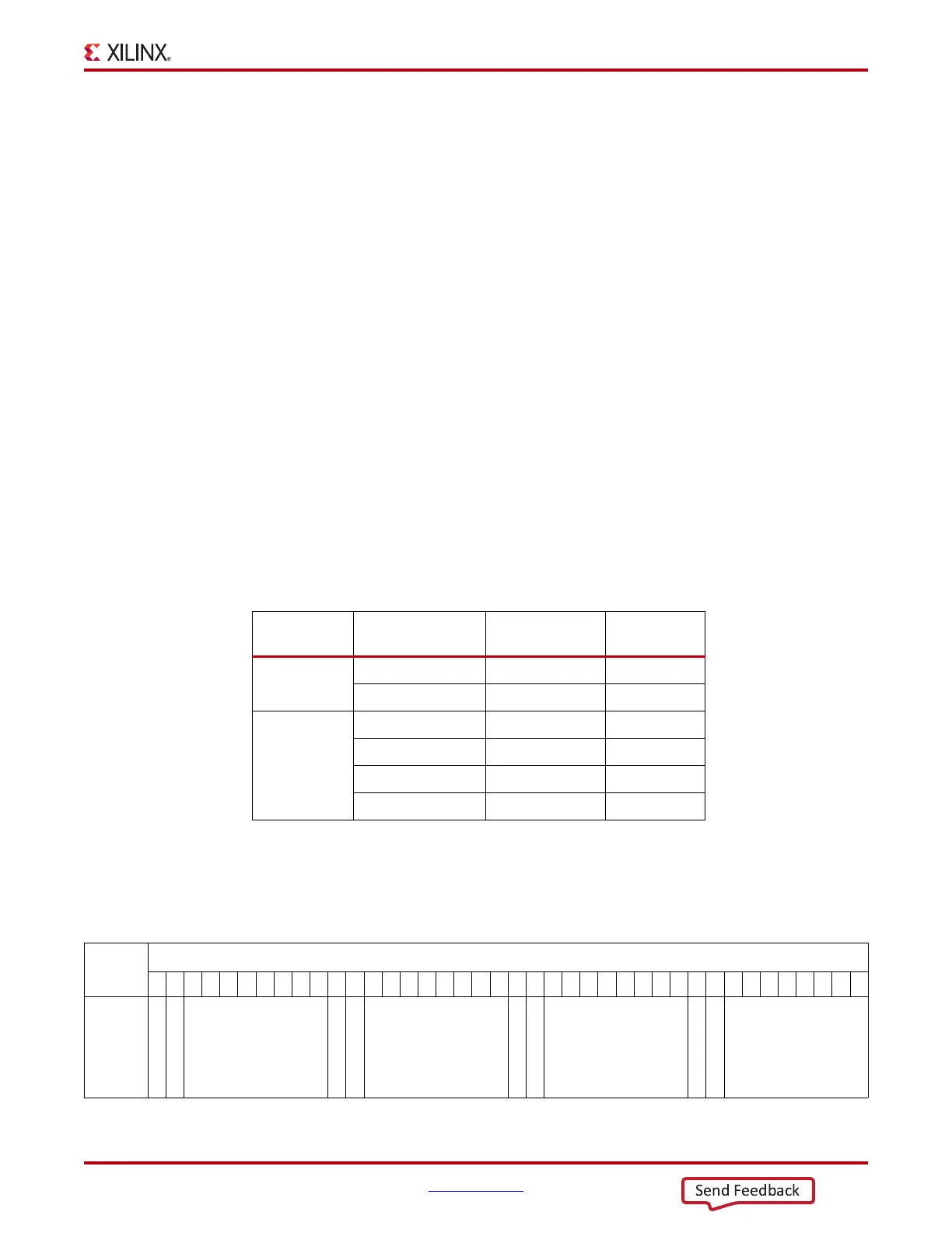
Table 4-43 shows how the interface width for the RX datapath is selected. 8B/10B decoding is
described in more detail in RX 8B/10B Decoder, page 170.
When the 8B/10B decoder is bypassed and RX_DATA_WIDTH is 20 or 40, the RXDISPERR and
RXCHARISK ports are used to extend the RXDATA port from 16 to 20 bits, or 32 to 40 bits.
Table 4-44 shows the data received when the 8B/10B decoder is disabled. When the RX gearbox is
used, refer to RX Gearbox, page 207 for data transmission order.
Table 4-43: FPGA RX Interface Datapath Configuration
RX8B10BEN RX_DATA_WIDTH
FPGA Interface
Width
Internal Data
Width
1
20 16 20
40 32 20
0
16 16 16
20 20 20
32 32 16
40 40 20
Table 4-44: RX Data Received When the 8B/10B Decoder is Bypassed
< < < Data Reception is Right to Left (LSB to MSB) < < <
3938373635343332313029282726252423222120191817161514131211109876543210
Data
Received
RXDISPERR[3]
RXCHARISK[3]
RXDATA[31:24]
RXDISPERR[2]
RXCHARISK[2]
RXDATA[23:16]
RXDISPERR[1]
RXCHARISK[1]
RXDATA[15:8]
RXDISPERR[0]
RXCHARISK[0]
RXDATA[7:0]

 Loading...


