Embedded Tri-Mode Ethernet MAC User Guide www.xilinx.com 61
UG074 (v2.2) February 22, 2010
Client Interface
R
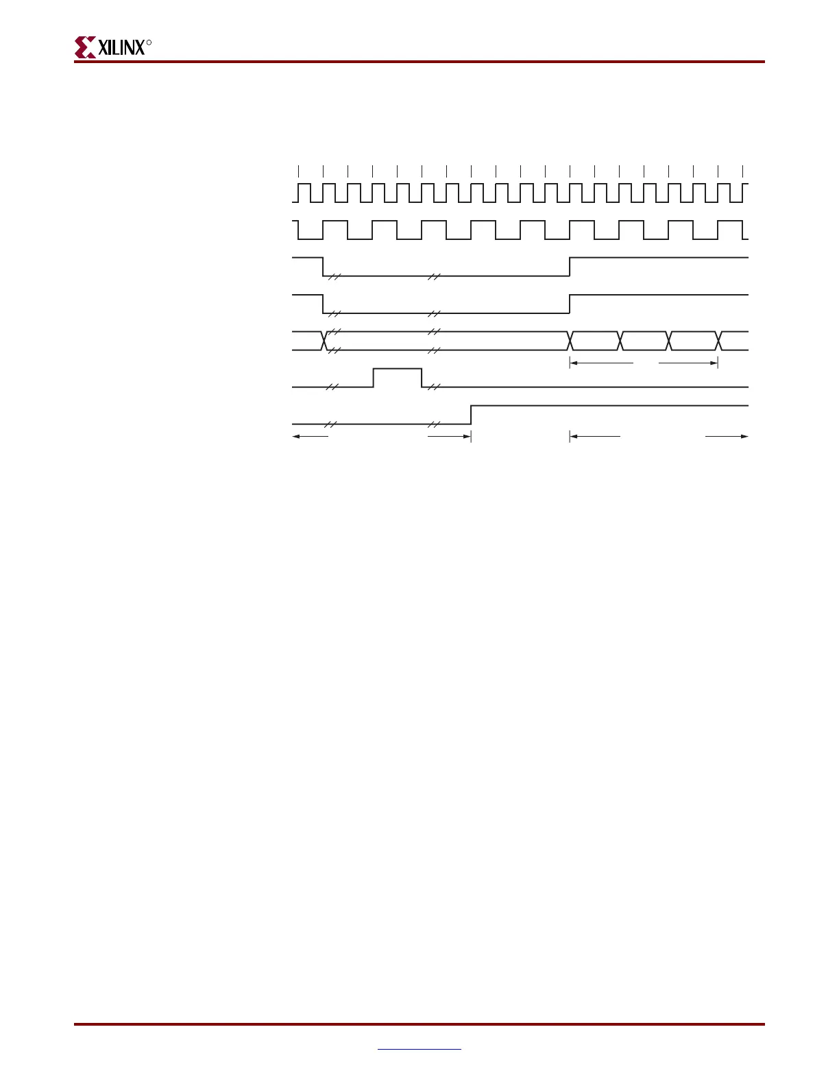
Figure 3-27 shows the timing diagram when a frame fails to match a valid location in the
AF (16-bit mode) and the frame drop signal is generated. The address filter is disabled in
this timing diagram.
Flow Control Block
The flow control block is designed to Clause 31 of the IEEE Std 802.3-2002 standard. The
Ethernet MAC can be configured to send pause frames to act upon the pause frame’s
reception during full-duplex operation. These two behaviors can be configured
asymmetrically (see “Configuration Registers,” page 74).
Requirement for Flow Control
Figure 3-28 illustrates the requirement for flow control. The Ethernet MAC on the right
side of the figure has a reference clock slightly faster than the nominal 125 MHz. The
Ethernet MAC on the left side of the figure has a reference clock slightly slower than the
nominal 125 MHz. This results in the Ethernet MAC on the left side of the figure not being
able to match the full line rate of the Ethernet MAC on the right side (due to clock
tolerances). The left Ethernet MAC is illustrated as performing a loopback
implementation; this results in the FIFO filling up over time. Without flow control, this
FIFO eventually fills and overflows, resulting in the corruption or loss of Ethernet frames.
Figure 3-27: Frame Matching Failed Timing Diagram (16-Bit Mode)
nn–4n–5 n–2 n–1n–3 n+1 n+2 n+3 n+4 n+5 n+6
CLIENTEMAC#RXCLIENTCLKIN
EMAC#CLIENTRXDVLD
PHYEMAC#RXCLK
EMAC#CLIENTRXD[15:0]
EMAC#CLIENTRXGOODFRAME
EMAC#CLIENTRXFRAMEDROP
Previous Frame
Passed
Current Frame
Dropped
DA
DA1, DA0 DA3, DA2 DA5, DA4
ug074_3_29_080805
EMAC#CLIENTRXDVLDMSW

 Loading...


