Embedded Tri-Mode Ethernet MAC User Guide www.xilinx.com 89
UG074 (v2.2) February 22, 2010
Host Interface
R
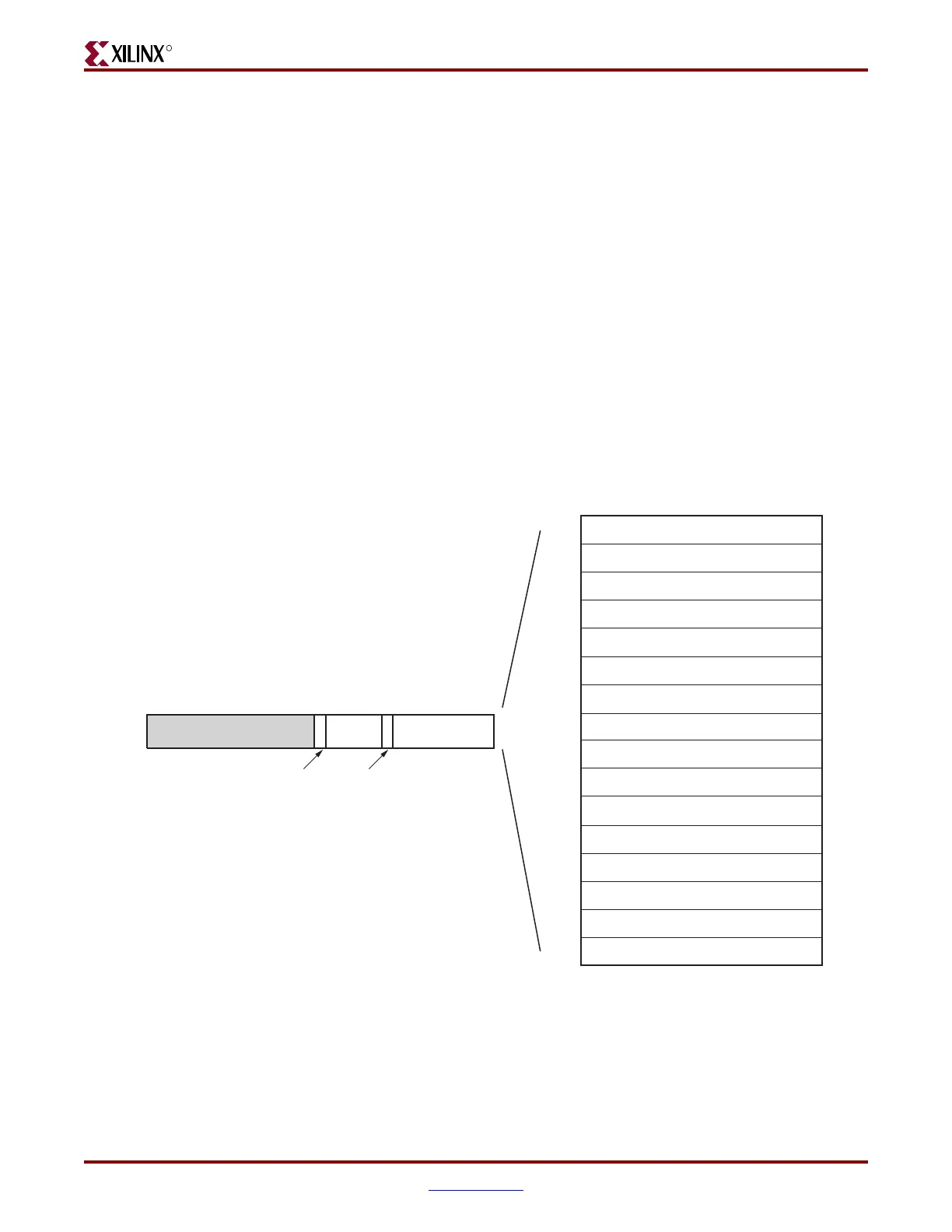
Description of Ethernet MAC Register Access through the DCR Bus
To write data to an Ethernet MAC register through the DCR bus, the host processor must
first write the data into the DCR dataRegLSW. The host processor then writes the EMAC0
or EMAC1 select bit, the write control bit, and the Ethernet MAC register address code into
the DCRcntlReg. The Ethernet MAC register address code in the cntlReg,
ADDRESS_CODE (Table 3-24), is translated into the corresponding Ethernet MAC register
address in the Ethernet MAC, and the address is output on the address bus
HOSTADDR#[9:0]. See Figure 3-39, page 73. The mapping of the ADDRESS_CODE field to
the set of Ethernet MAC registers is also shown in Figure 3-44.
The DCR registers (dataRegMSW, dataRegLSW, cntlReg, and RDYstatus) and the DCR
bridge registers (IRSTATUS, IRENABLE, and MIIMWRDATA) use the big endian bit
numbering convention. However, the Ethernet MAC host registers, such as Receiver
Configuration (Word 0) (host address 0x200) register, use the little endian bit numbering
convention. In the DCR bridge implementation, there is no conversion to or from big
endian to little endian. The bit positions are mapped directly in a one-to-one
correspondence, (big endian bit [0] is mapped directly to little endian bit [31], big endian
bit [1] is mapped directly to little endian bit [30] and onward).
The decode of the address code also generates the control signals MIIMSEL#, REQ#, and
OPCODE#[1:0] (see Figure 3-39, page 73). Data in the dataRegLSW is output on the
WRD#[31:0]. These signals are output to EMAC0 or EMAC1 when selected by the
Figure 3-44: DCR to Ethernet MAC Host Interface Memory Map
ug074_3_48_082205
Flow Control Configuration
RGMII/SGMII Configuration
Transmitter Configuration
Receiver Configuration (Word 0)
310
0x200
0x240
0x280
0x2C0
Ethernet MAC Mode Configuration
0x300
MSB
LSB
Receiver Configuration (Word 1)
DCR-to-Ethernet MAC
Host Interface Memory Map
0x320
Management Configuration
0x340
Unicast Address (Word 0)
0x380
Unicast Address (Word 1)
0x384
Multicast Address (Word 0)
0x388
Multicast Address (Word 1)
0x38C
Address Filter Mode
0x390
IRSTATUS
IRENABLE
MDIO Write Data
MIIMCNTL
0x3A0
0x3A4
0x3B0
0x3B4
ADDRESS_CODERESERVED
0x2
DCR Offset
0162131
MSB
LSB
22
WEN EMAC1 SEL

 Loading...


