168
Appendix 4. Q&A
Q1: What is BB and run?
1. BB standby state, without enabling, the motor is in the state of power failure.
2. Run running state, with enabling, the motor is in the power on state.
Q2: How to check and set the parameters?
Refer to chapter 4.6
Q3: How to change the parameters in enabled status?
P5-20=0000, enabling is invalid, P5-20=0010, enabling when power on, no need to power on again.
The default value is 0001, which means input signal from SI1, SI1 connects to low voltage, +24V connects to high
voltage (refer to chapter 5.2.2)
Q4: How to restore out of factory settings?
P5-20=0000 enabling is invalid, F0-01=1.
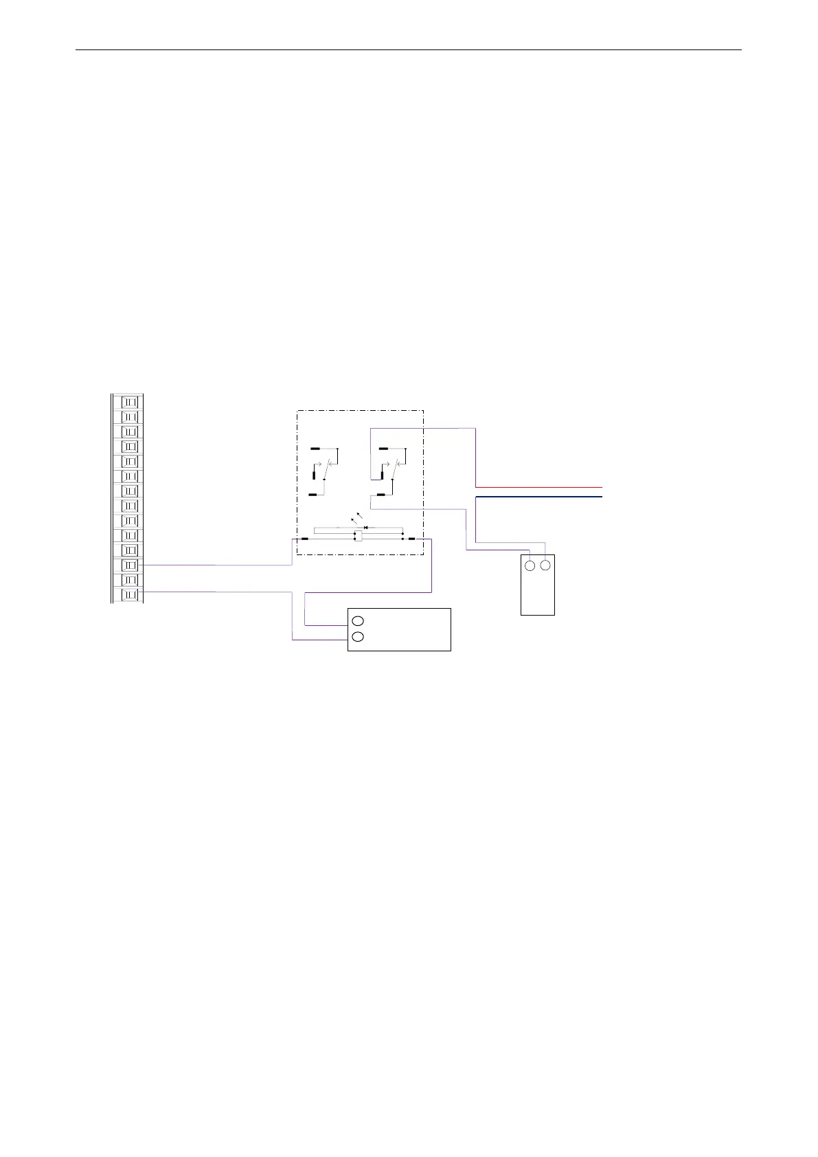
Q5: How to wiring for brake motor? How to modify parameters for slight slip of brake motor after power failure?
1. P5-44 defines the terminal of the brake output signal. As shown in the figure above, the SO1 controls brake,
that is, P5-44 = 0001.
2. Extend the delay time of servo OFF P5-07 (default 500ms), and the waiting time of braking instruction P5-09 is
set to 0, which can be responded.
Q6: The initial direction is not what I want. How can I change it through a servo driver?
Change the initial direction by modifying P0-05, set the value to 0 or 1, and take effect after re-energizing. (For
mode 2, 4, 6, 7 only). If the internal speed mode (mode 3) is used, the positive and negative values of the speed
setting can be changed.
Q7: How do the two modes switch to each other?
Both P0-01 main mode and P0-02 sub-mode set the required mode. P5-30=0002 and SI2 are defined as mode
switching terminals. When the SI2 terminal has no signal, it runs according to the set mode in the main mode
P0-01. When the SI2 terminal has signal input, it runs according to the set mode in the sub-mode P0-02.
Note: SI2 terminal signal can be switched only if it is a constant ON signal.
Q8: What is the connection mode between PLC and servo?
1. NPN low-level output PLC: Y0 pulse connects P-, Y1 direction connects D-, +24V connects P+24, D+24.
(Xinje PLC as an example)
PNP high-level output PLC: Q0.0 pulse connects P+24, Q0.2 direction connects D+24, 0V connects P-, D-.
(Siemens PLC as an example) as follows:
 Loading...