Home
Xinje
Servo Drives
DF3E Series
Xinje DF3E Series User Manual
5
of 1
of 1 rating
189 pages
Give review
Manual
Specs
To Next Page
To Next Page
To Previous Page
To Previous Page
Loading...
1
1
Selection of servo
system
1.1 Selection of
servo driver
1.1.1 Model name
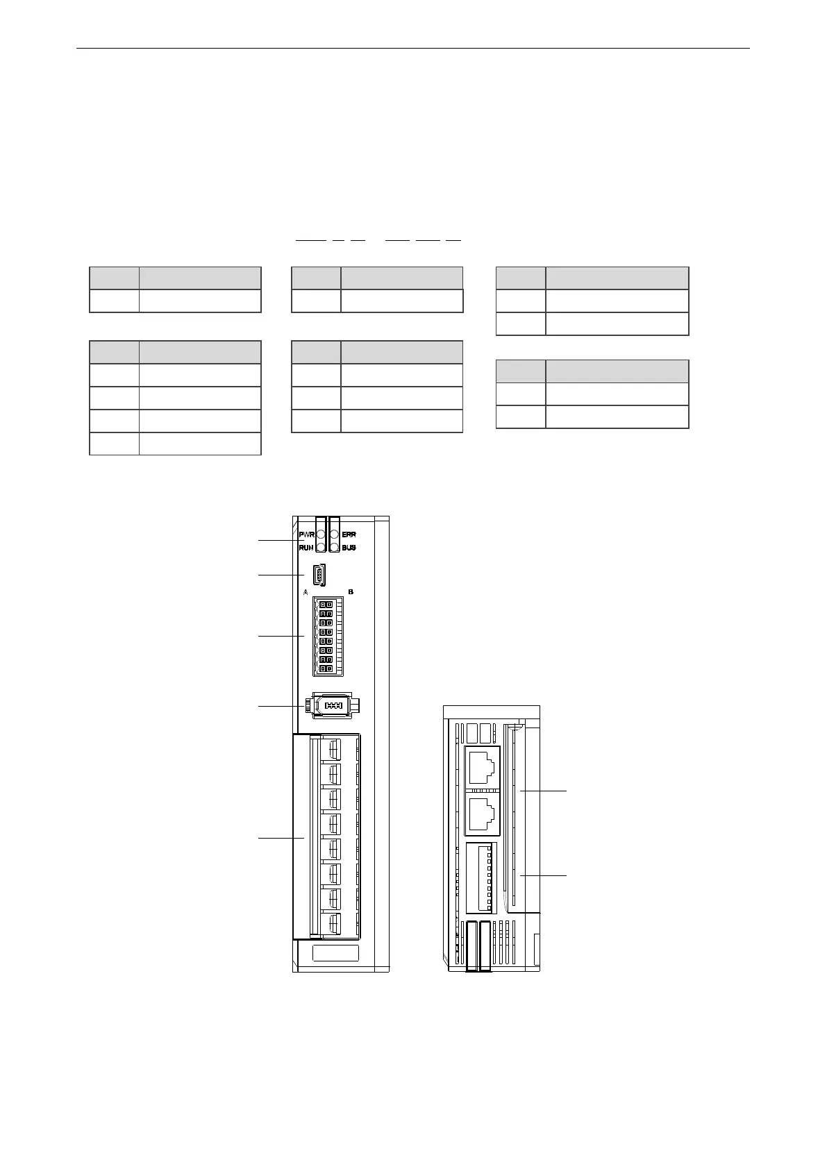
1.1.2 Description of each part
Note:
this driver
has
no
panel, so
it
can't operate
the
panel. It
needs
to
connect the
ca
ble of
Xinje
servo DB9
with
USB, and use t
he Xinje serv
o software.
DF
3
E
-
04
10
Z
Code
Product name
DF
Servo driver
Code
Rated output
current
05
5
A
10
10
A
20
20
A
Code
Rated output
power
01
100
W
02
200
W
04
400
W
07
750
W
Code
Product series
3
Series number
Code
Specificati
on
Z
Servocan drive the brake
Servo cannot drive the brake
Code
Control function
E
Pulse, RS485, Canopen
、
C
EtherCAT
Power LED and a
larm LED
Enable LED an
d Can communicati
on LED
CN1
:
RS2
32 port
CN2: signal I
O port
CN3: communicat
ion
encoder feedbac
k
CN4: power sup
ply input
Power cable outp
ut
CN0: Type E-CANo
pen&RS485
Type C-EtherCAT
DIP sw
itch
8
10
Table of Contents
Table of Contents
5
Confirmation on Product Arrival
8
Selection of Servo System
9
Selection of Servo Driver
9
Model Name
9
Description of each Part
9
Performance Specification
10
Servo Motor Selection
11
Model Name
11
Description of each Part
11
Cable Selection
12
Model Name
12
Description of each Part
13
Selection of Other Accessories
15
Selection of Regenerative Resistance
15
Fuse Selection
15
Installation of Servo System
16
Servo Driver Installation
16
Installation Site
16
Environment Condition
16
Installation Standard
16
Servo Motor Installation
18
Environment Condition
18
Installation Cautions
18
Installation Environment
20
Servo Cable Installation
20
Cable Selection
20
Xinje Cable Specification
21
Servo Driver Dimension
24
Servo Motor Dimension
24
Wiring of Servo System
26
Main Circuit Wiring
26
Servo Driver Terminal Arrangement
26
CN4 Terminals
27
CN2 Terminals and DIP Switch
27
Communication Port
28
Classification and Function of Cn0 Signal Terminals
29
Pulse Signal
29
Input Signal (Without Brake)
29
SO Output Signal
30
Operation of Servo System
31
Control Mode Selection and Switching
31
Control Mode Selection
31
Control Mode Switching
31
Basic Function Setting
32
Jog Operation
32
Servo Enable Setting
33
Rotation Direction Switching
33
Stop Mode
34
Power-Off Brake
36
Braking Setting
38
Position Control
40
General Position Control
40
Position Control (External Pulse Command)
49
Position Control (Internal Command)
50
Speed Mode General Control
58
Speed Control (Internal Speed)
60
Speed Control (Pulse Frequency Command)
63
Torque Control
64
Torque Control (Internal Setting)
64
Bus Control
65
Object Dictionary Region Assignment
65
Cia402 Motion Control Explanation
72
CIA402 Motion Control Mode
82
Absolute Value System
103
Absolute System Setting
103
Replace the Battery
103
The Upper Limit of Turns
104
Read Absolute Position through Communication
105
Reset Absolute Position
106
Auxiliary Functions
106
Anti-Blocking Protection
106
Torque Limit
107
Speed Limit
108
I/O Signal Distribution
108
Output Terminal Function
109
Input Terminal Function
113
Time Limit Curve of Overload Protection
115
Servo Gain Adjustment
116
Overview of Servo Gain Adjustment
116
Overview and Process
116
The Difference of These Adjustment Modes
117
Model Loop Control
117
Torque Disturbance Observation
119
Rotary Inertia Presumption
119
Overview
119
Notes
119
Operation Tool
120
Operation Steps
120
Fast Adjustment
122
Overview
122
Fast Adjustment Steps
122
Rigidity Level Corresponding Gain Parameters
122
Notes
123
Auto-Tuning
124
Overview
124
Notes
124
Operation Tools
124
Internal Instruction Auto-Tuning Steps
125
External Instruction Auto-Tuning Steps
129
Related Parameters
133
Manual Adjustment
134
Overview
134
Adjustment Steps
134
Gain Parameters for Adjustment
135
Vibration Suppression
137
Overview
137
Operation Tools
137
Vibration Suppression (PC Software)
137
Vibration Suppression (Manual Setting)
138
Notch Filter
138
Gain Adjustment
141
Load Shaking
141
Vibration
141
Noise
141
Alarm
142
Alarm Code List
142
Analysis of Alarm Types
144
Appendix
154
Appendix 1. Group Pparameters
154
Monitoring Parameters
168
Appendix 3. Modbus Address List
171
Q&A
176
Appendix 5. General Debugging Steps
178
Appendix 6. Application Example
179
Appendix 7. Servo General Mode Parameters
181
Appendix 7.1 Basic Parameters
181
Appendix 7.2 External Pulse Position Mode General Parameters
181
Appendix 7.3 Internal Position Mode General Parameters
181
Appendix 7.4 Internal Torque Control General Parameters
182
Appendix 7.5 Internal Speed Control General Parameters
182
Appendix 7.6 External Pulse Speed Control General Parameters
182
Appendix 8. Torque-Speed Characteristic Curve
184
Appendix 9. List of Model Selection and Configuration
185
Appendix 10. Servo Software
186
Appendix 10.1 Communication between Servo Software and Servo Driver
186
Appendix 10.2 Start [Driver Communication]
186
Appendix 10.3 Close [Driver Communication]
186
Appendix 10.4 [Driver Communication] Interface
187
5
Based on 1 rating
Ask a question
Give review
Questions and Answers:
Need help?
Do you have a question about the Xinje DF3E Series and is the answer not in the manual?
Ask a question
Xinje DF3E Series Specifications
General
Brand
Xinje
Model
DF3E Series
Category
Servo Drives
Language
English
Related product manuals
Xinje DS3 Series
152 pages
Xinje DS5C Series
121 pages
Xinje DS5F Series
210 pages
Xinje DS5K Series
236 pages
Xinje DS2-43P0-AS
99 pages
Xinje DS2-21P5-AS
99 pages
Xinje DS2-22P3-AS
99 pages
Xinje DS5L1 Series
171 pages
Xinje DS5F-20P7-PTA
210 pages
Xinje DS5F-21P5-PTA
210 pages
Xinje DS5L1-20P4-PTA
171 pages
Xinje DS3 series servo
41 pages
 Loading...

