23
4 Operation of servo system
4.1 Control mode selection and switching
4.1.1 Control mode selection
Servo can combine two control modes and switch between them. By switching freely between mode 1 and mode 2
through the / C-SEL signal, more complex control requirements can be satisfied.
Position control is to input the pulse train command into the servo unit and move it to the target position. The
position instruction can be given by the combination of external pulse input, the total number of internal position
instructions and speed limit. The position is controlled by the number of input pulses, and the speed is controlled
by the frequency of input pulses. It is mainly used in the occasions requiring positioning control, such as
manipulator, grinder, engraving machine, CNC machine, etc.
Speed control is to control the speed of machinery by speed command. The servo driver can control the
mechanical speed quickly and accurately by the speed command given by digital, analog voltage or
communication.
Torque control is to control the output torque of motor by torque command. Torque command can be given by
digital, analog voltage or communication. The current of servo motor is linear with torque, so the control of
current can realize the control of torque. The torque control mode is mainly used in the devices with strict
requirements on the stress of materials, such as some tension control occasions such as winding and unwinding
devices. The torque setting value should ensure that the stress of materials is not affected by the change of
winding radius.
The bus mode is to control the motor operation through the bus command to meet the needs of customers. The
main line and the slave line run real-time, data transmission, and data acquisition and control of the underlying
equipment.
4.1.2 Control mode switching
Control mode switching means that the working mode of servo driver can be switched between mode 1 and mode
2 through external input signal /C-SEL during normal operation of servo.
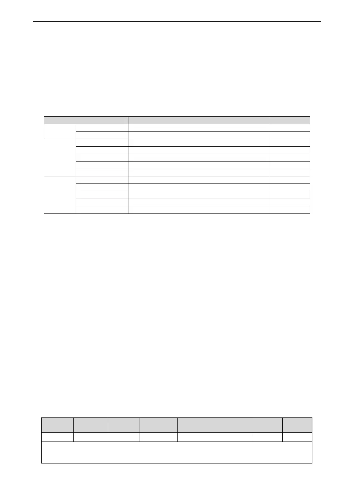
◼ Related parameter
Parameter range n.0000-0014, can be distributed to other input terminal through P5-30.
If the control mode needs to be switched through SI2 input signal, P5-30 can be set to n.0002/0012. Refer
to section 3.2.2 for hardware wiring details.
 Loading...

