6 REAR AXLE AND BRAKE 6 REAR AXLE AND BRAKE
EF494T TM 06/2011 edition
6.2 DISASSEMBLY AND ASSEMBLY
6.2.1 Differential system
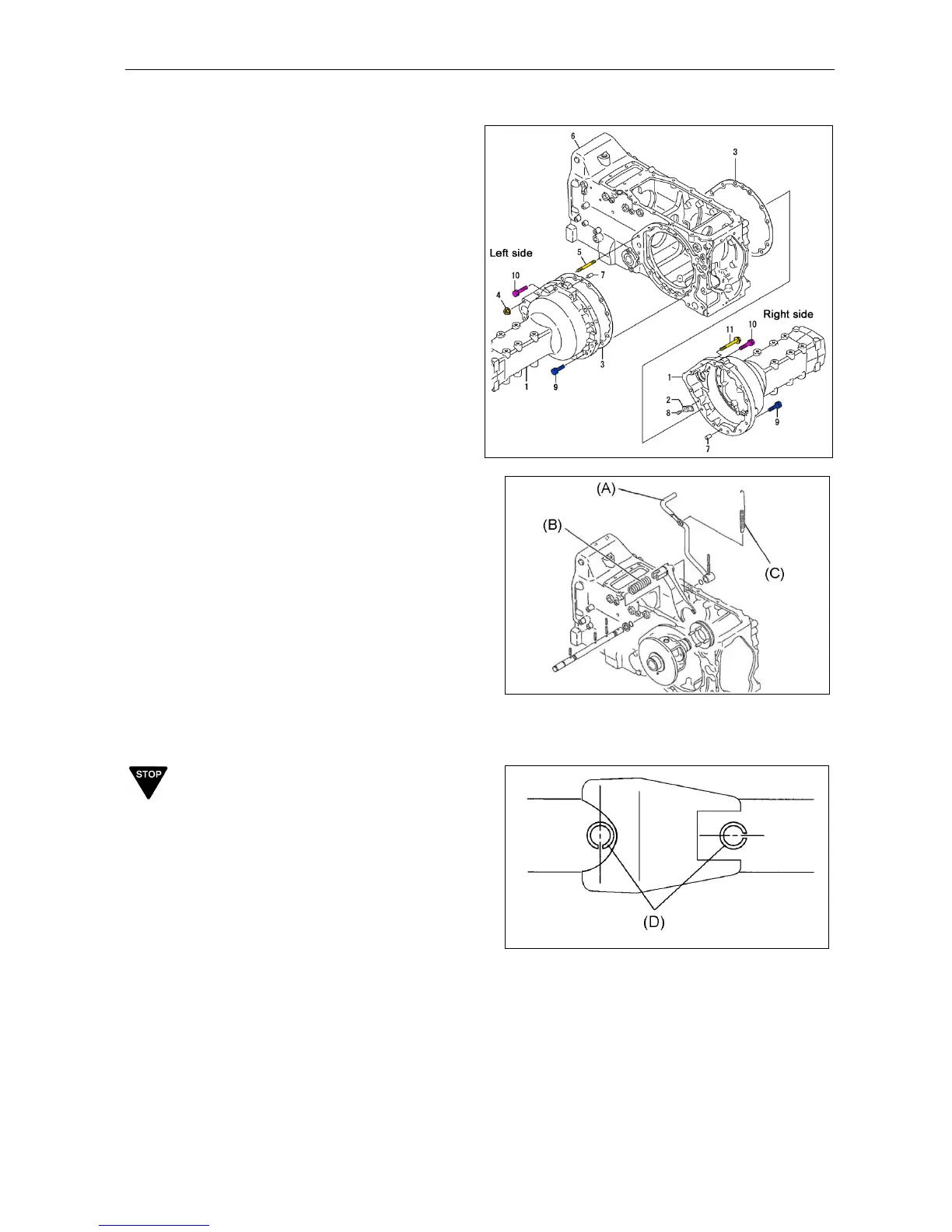
(1) Remove the hydraulic cylinder case.
(2) Remove the left rear axle housing
assembly.
4: Nut M10 x 2 pieces
9: Bolt M12 x 40 x 8 pieces
10: Bolt M12 x 50 x 2 pieces
Note:
Refer to “2.6.3 Rear axle” for details.
(3) Remove the differential lock fork. To
assemble, make sure the return spring is
positioned as shown to the right.
(A) Differential lock pedal
(B) Differential lock fork
(C) Return spring (Note direction)
IMPORTANT
When attaching the spring pins of the differential
pedal shaft, match the match positions as shown
in the figure below.
 Loading...