9 HYDRAULIC LIFT UNIT 9 HYDRAULIC LIFT UNIT
EF494T TM 06/2011 edition
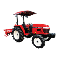
Caution when assembling
The lift arm, lift crank and lift shaft on the
hydraulic cylinder casing have alignment marks.
The photos show white paint on the mark, for
reference.
Lift arm and lift shaft
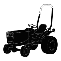
Lift shaft and shift crank
(A) Alignment mark
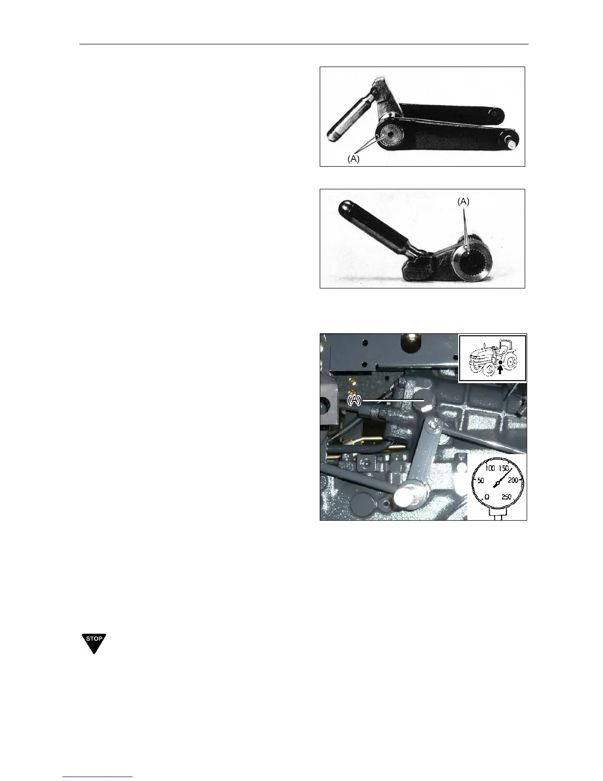
9.2.3 Main relief pressure
(1) Remove the single output plug lower the
seat.
(2) Attach the hydraulic pressure tester to the
output block.
Note:
Size: 3/4-16 UNF
(3) Start the engine and lower the hydraulic lift
arm.
(4) Close the stop valve, increase the engine
speed, and set the control lever to the
position of UP. Read the tester when relief
valve chattering noise is heard.
Specified pressure: 170-178 kgf/cm
2
(16.7-17.4
MPa)
(A) Attach the hydraulic pressure tester here.
If pressure is too high: Remove shims.
If pressure is too low: Insert shims.
Shim's effect:
Shim 0.25 mm thick: 3.9 kgf/cm
2
Shim 0.5 mm thick: 7.7 kgf/cm
2
Shim 1.0 mm thick:15.5 kgf/cm
2
IMPORTANT
Never adjust relief valve more than specified
pressure or it causes serious trouble on the
hydraulic system.
 Loading...