1-1
IM 04L42B01-01E
Overview of Functions
1
1.1 InputSection
Measurement Channel
• NumberofMeasurementChannelsandScanInterval
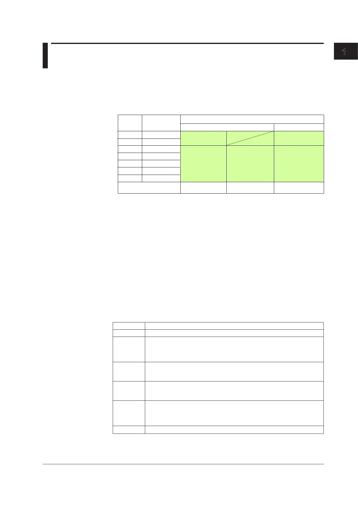
The DX samples the input signals on the measurement channels at the scan interval
to obtain the measured values. The table below shows the relationship between the
number of measurement channels and the scan interval.
DX2004
DX2008
DX2010
DX2020
DX2030
DX2040
DX2048
25 ms
125 ms
125 ms
250 ms
2 s, 5 s
4
8
10
20
30
40
48
Fast Sampling Mode*Normal Mode
Measurement
Channels
Model
Scan Interval
Integration time of the A/D
converter
60 Hz/50 Hz/100 ms
60 Hz/50 Hz
600 Hz (fixed)
* Not available on models equipped with external input channels (/MC1 option) or
when the multi batch function (/BT2 option) is being used.
1 s, 2 s, 5 s
For the setting procedure, see section 3.1.
• IntegrationTimeoftheA/DConverter
The DX uses an A/D converter to convert the sampled analog signal to a digital
signal. By setting the integration time of the A/D converter to match the time period
corresponding to one cycle of the power supply or an integer multiple of one cycle, the
power supply frequency noise can be effectively eliminated.
• Because100msisanintegermultipleof16.7msand20ms,thissettingcanbeusedto
eliminate the power frequency noise for both frequency, 50 Hz and 60 Hz.
• Infast sampling mode, the performance of eliminating power frequency noise is worse than
in normal mode. We recommend that you use normal mode when making measurements in
an environment affected by power frequency noise.
For the setting procedure, see section 3.1.
InputTypeandComputation
You can make measurements using the following input types.
*1 Item sold separately. For example, a 250-Ω shunt resistor is used to convert the signal
to 1 to 5 V for 4-20 mA input.
*2 /N3 option.
*3 /N1 option.
Input Type Description
DC voltage Measures a DC voltage in the range of ±20 mV to ±50 V.
DC current A shunt resistor
*
1
is attached to the input terminal. The current signal is converted
to a voltage signal and measured. The measurable range is the range equivalent
to the “DC voltage” range indicated above after converting the current to the
voltage signal.
Thermocouple Measures temperature corresponding to each type: R, S, B, K, E, J, T, N, W,
L, U, and WRe3-25. Measurement is possible on other thermocouples
such as PR40-20 and PLATINEL
*
2
.
RTD Measures temperature corresponding to each type: Pt100 and JPt100.
Measurement is possible on other RTDs such as Cu10 or Cu25
*
3
and Pt50 or
Ni100
*
2
.
ON/OFF input Displays the contact input or voltage input signals by correlating them to 0% or
100% of the display range.
Contact input: Closed contact is ON (1). Open contact is OFF (0).
Voltage input: Less than 2.4 V is OFF (0). Greater than or equal to 2.4 V is ON (1).
Pulse input
*
4
Counts the pulses.
Chapter1 OverviewofFunctions

 Loading...