Fieldbus control through the embedded fieldbus interface (EFB) 393
Set up the drive manually.
1. Power up the drive.
The software recognizes the CANopen interface module that is connected to the
drive. The software checks that the CANopen adapter is attached.
2. Do not press OK. Set up the parameters listed in the table CANopen parameters.
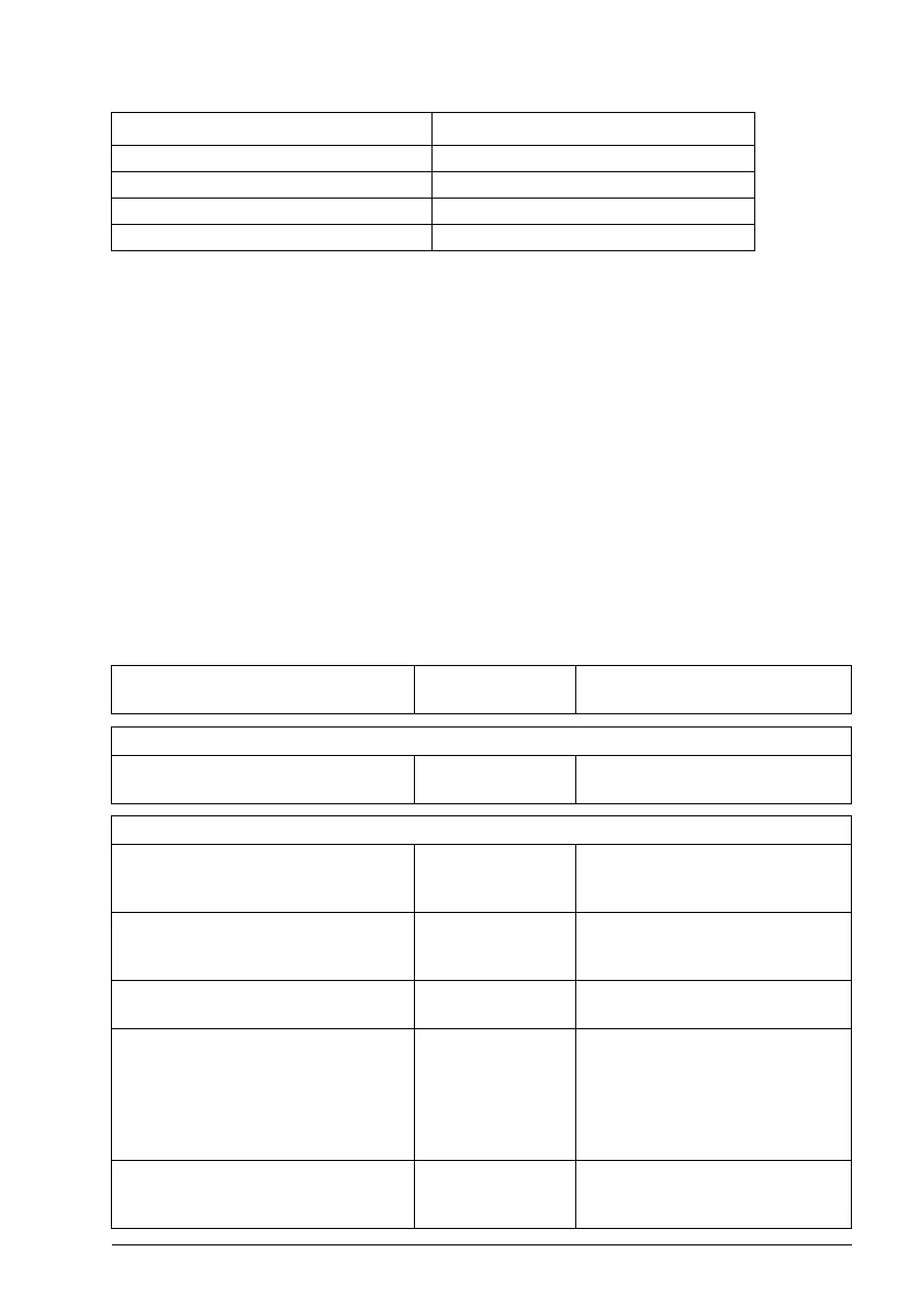
3. Set up the drive for the embedded fieldbus communication with the parameters
shown in the table below (CANopen parameter settings for embedded fieldbus
interface).
The Setting for fieldbus control column shows either the value to use, or the
default value. The Function/Information column describes the parameter.
Note: The CANopen module must be connected to the drive for the CANopen
parameters to be visible (58.01 = [3] CANopen).
CANopen parameter settings for embedded fieldbus interface
28.23 Constant frequency sel2 Not selected
28.71 Freq ramp set sel Acc/Dec time 1
31.11 Fault reset selection DI1
58.01 Protocol enable CANopen
Parameter
Setting for
fieldbus control
Function/Information
COMMUNICATION INITIALIZATION
58.01 Protocol enable CANopen Initializes embedded fieldbus
communication.
EMBEDDED MODBUS CONFIGURATION
58.03 Node ID 3 (default) Node address. There must be no
two nodes with the same node
address online.
58.04 Baud rate 125 kbps (default) Defines the communication
speed of the link. Use the same
setting as in the master station.
58.14 Communication loss action Fault (default) Defines the action taken when a
communication loss is detected.
58.23 Configuration location CAN objects Bus: PDOs are configured by the
fieldbus master with SDO.
Drive parameters: PDO
configuration is determined by
drive parameters 58.76, 58.93,
and 58.101...58.124.
58.25 Control profile CiA 402 (default) Selects the control profile used by
the drive. See section Basics of
the user interface.
Parameter Setting

 Loading...


