VOLTAGE SENSO R S PRIM AR Y TESTING
30 1VLG 50 00 17 C
4.3.2 Voltage sensor installed in the cable compartment
Step 1/7
Verify sensor parameters set in the protection relay with the sensor rating plates placed on
the circuit breaker door.
Figure 41: Example of a voltage sensor label
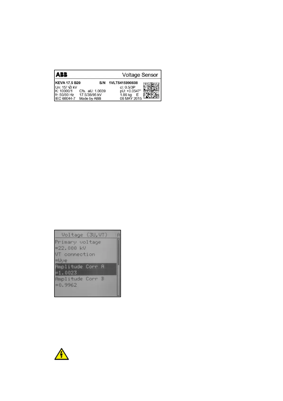
On the protection relay LHMI go to -> Main Menu/Configuration/Analog inputs/
Voltage (3U, VT)
– Primary voltage = nominal voltage of the network
– VT connection = Wye (star connection)
– Amplitude Corr A = sensor rating plate, phase A
– Amplitude Corr B = sensor rating plate, phase B
– Amplitude Corr C = sensor rating plate phase C
– Division ration = 10 000
– Voltage input type = CVD sensor
– Angle Corr A = sensor rating plate, phase A
– Angle Corr B = sensor rating plate, phase B
– Angle Corr C = sensor rating plate, phase C
Figure 42: Voltage sensor parameters
Step 2/7
Isolate tested phases. Remove the circuit breaker out of the switchgear panel. Any high volt-
age cables terminated at the panel should be disconnected for safety reasons.
Step 3/7
If there is the high voltage on busbars, secure top shutter with a padlock

 Loading...