SE CO ND AR Y T EST ING O F PR OT E CT IO N R E LAYS SE CO NDAR Y T E ST S ETU P S
1VLG5 00 0 17 C 73
Test Setup for Megger – 1 phase
For high setting of overcurrent protection, you may need to apply at max. 93.75 Vrms, 50 Hz
which represent 50 kA symmetrical short circuit current on the primary side. Therefore, it is
recommended to use high voltage outputs situated on the front side. These can be con-
nected to the protection relay as a 1 phase tester.
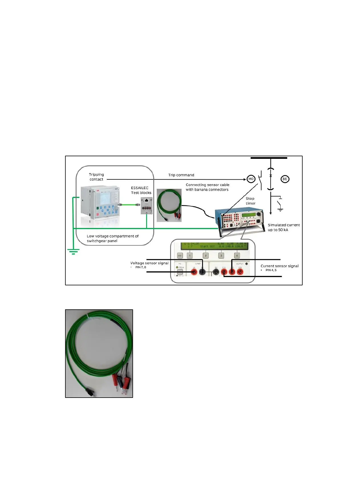
Step 1/3
The protection relay and tester must be grounded on the same potential.
Step 2/3
Megger tester is connected via connecting cable terminated with banana connectors and
RJ45 connector on the other one end to the ESSAILEC
®
test block or directly to the protection
relay if the ESSAILEC
®
test block is not installed. Wires for the voltage sensor are connected to
the Uref output as Phase – Earth voltage. Wires for the current sensor are connected to the
UL1, UL2 voltage output.
Figure 114: 1 phase test setup for the Megger tester
Figure 115: Connecting cable with RJ45 connector and banana contacts (it is available on cli-
ent request)

 Loading...