INT ER LOCK S BE T W EE N PA NELS AP PAR ATUS CO NTR O L T E STING
46 1VLG 5000 17 C
Step 1/5
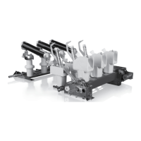
All circuit breakers must be in the test position. Check their status on the protection relay
LHMIs on the Single line diagram.
Figure 67: Single line diagram, the circuit breaker is in the test position
Step 2/5
Check the busbar earthing switch shutter. It can be open and the crank inserted.
Step 3/5
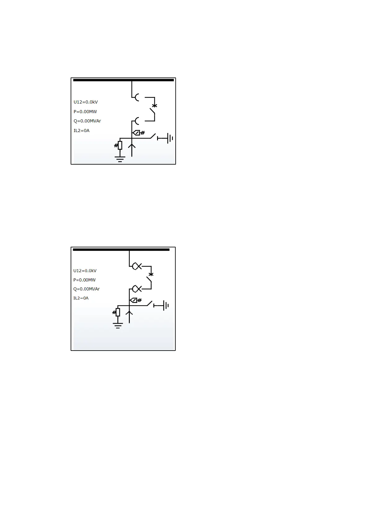
Move the circuit breaker out of the test position about a half-turn of the crank in one feeder.
Check the circuit breaker position on the protection relay LHMI.
Figure 68: Single line diagram, the circuit breaker is in the intermediate position
Step 4/5
Check the busbar earthing switch shutter. It cannot be open (crank cannot be inserted).
Step 5/5
Repeat step 3 and 4 for each feeder in the relative section

 Loading...