PRIM AR Y TESTING VOLTAGE SENSO R S
1VLG5 00 0 17 C 33
4.3.3 Voltage sensor installed on busbars
Step 1/8
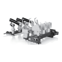
Verify sensor parameters set in the protection relay with the sensor rating plates placed on
the circuit breaker door.
Figure 45: Example of a voltage sensor label
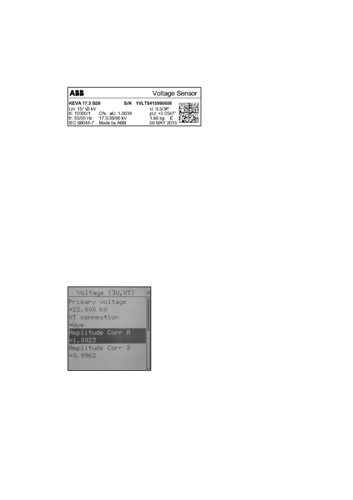
On the protection relay LHMI go to -> Main Menu/Configuration/Analog inputs/Voltage (3U,
VT)
– Primary voltage = nominal voltage of the network
– VT connection = Wye (star connection)
– Amplitude Corr A = sensor rating plate, phase A
– Amplitude Corr B = sensor rating plate, phase B
– Amplitude Corr C = sensor rating plate, phase C
– Division ration = 10 000
– Voltage input type = CVD sensor
– Angle Corr A = sensor rating plate, phase A
– Angle Corr B = sensor rating plate, phase B
– Angle Corr C = sensor rating plate, phase C
Figure 46: Voltage sensor parameters
Step 2/8
Isolate the whole bus section. All circuit breakers belong to the relative busbar section move
into the test position.
Step 3/8
Select one outgoing switchgear panel in the section to apply voltage on the main bus. Re-
move the circuit breaker out of the switchgear panel and close the earthing switch

 Loading...