INT ER LOCK S BE T W EE N PA NELS AP PAR ATUS CO NTR O L T E STING
58 1 VLG5000 17 C
Step 1/6
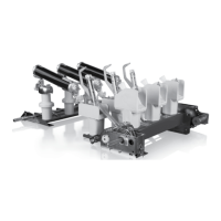
Move all circuit breaker trucks into the service position in the relative section. Check all the
circuit breakers trucks status on the protection relay LHMIs.
Figure 88: Single line diagram, the circuit breaker is in the service position
Step 2/6
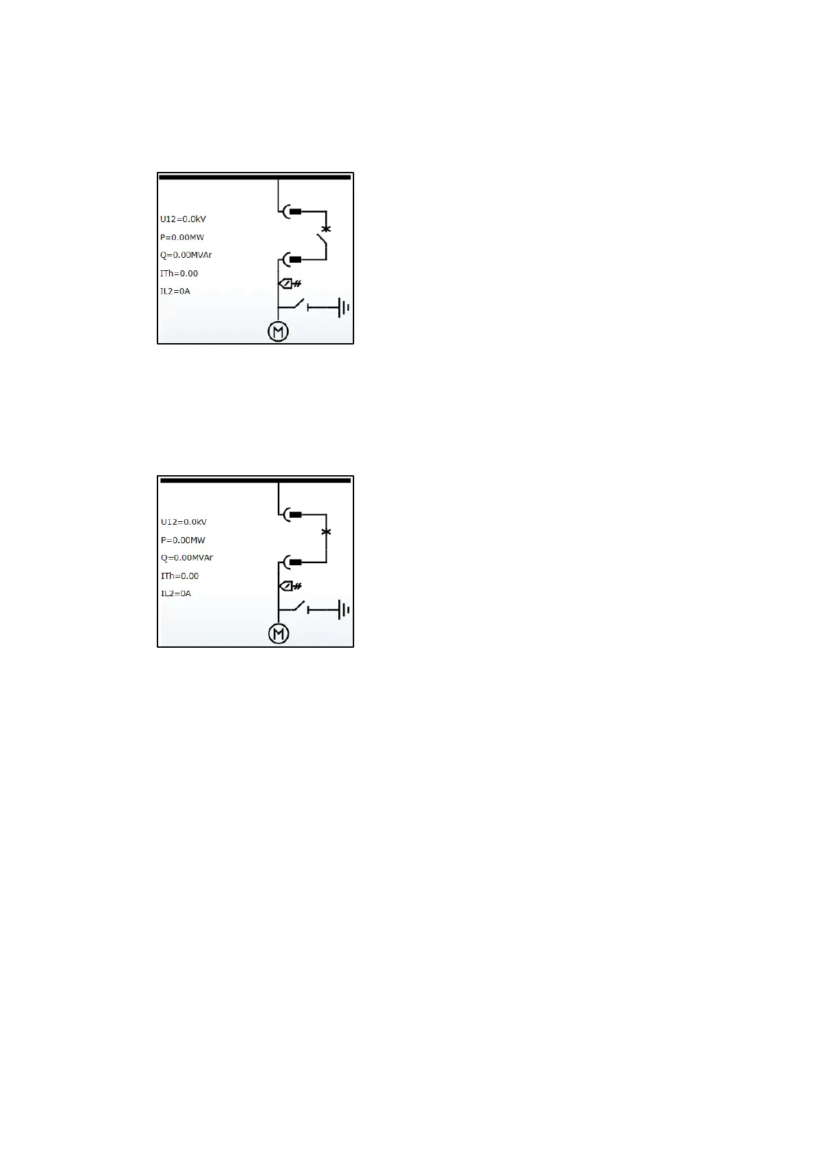
Close all circuit breakers in the relative section. Check all the circuit breakers status on the
protection relay LHMIs.
Figure 89: Single line diagram, the circuit breaker is closed and in the service position
Step 3/6
Select the feeder to be tested. Simulate a trip of the first flap (order of flap to be tested no
matter). Bring potential to the binary input for a short time. The circuit breaker must trip and,
according to inter-trip logic scheme, forward the trip command to the upstream breaker (In-
comer, Generator and Bus tie). The upstream circuit breaker must trip immediately all feeders
in the relative section shall trip at the same time if inter-trip is designed.
Step 4/6
Check interlocking logic. Clear Lockouts
Step 5/6
Repeat step 3 for next two flaps in the same feeder.
Step 6/6
Repeat steps 2 to 5 for all feeders.

 Loading...