SE CO ND AR Y T EST S ETU P S SE CO ND AR Y T EST ING O F PR OT E CT IO N R E LAYS
74 1VLG5000 17 C
Step 3/3
Simulate high currents on the current sensor input via the front voltage outputs L1U, L2U.
– U1 = U2 with 180° phase shift (symmetrical source)
Simulate voltage on the voltage sensor input via the front voltage output U4, NU.
– U4 =
𝑈𝑛
√
3
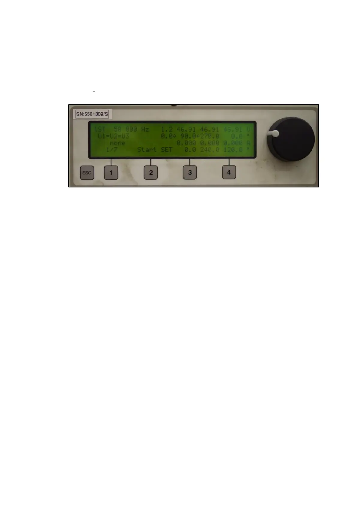
Figure 116: Setting of high voltage analogue outputs on the Freja 300 HMI

 Loading...