INT ER LOCK S BE T W EE N PA NELS AP PAR ATUS CO NTR O L T E STING
48 1VLG5 000 17 C
Step 1/4
All circuit breakers in the relative section are in the test position. Check the circuit breakers
status via the protection relay LHMIs.
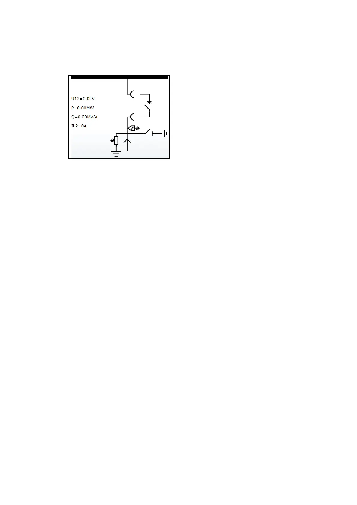
Figure 71: Single line diagram, the circuit breaker is in the test position
Step 2/4
Check the busbar earthing switch shutter. It can be open and the crank inserted.
Step 3/4
Fix the shutter in the open position.
Step 4/4
Check that no circuit breakers in the section can be moved out of the test position no more
than a half turn of the crank.

 Loading...