AP PAR ATUS CO NTR O L T E STI NG PA N E L INT ER N A L I NT ER LO C KING
1VLG5 00 0 17 C 37
Step 2/6
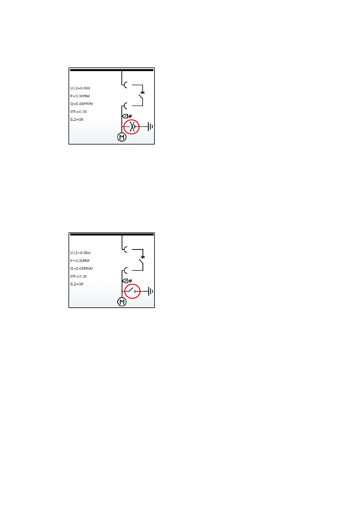
Insert the earthing switch crank on the shaft. Check the status on the protection relay LHMI.
Figure 52: Single line diagram, the earthing switch shutter is open
Step 3/6
Check that the circuit breaker cannot be moved into service position when the earthing
switch crank is inserted.
Step 4/6
Remove the earthing switch crank from the shaft. The shutter must be closed. Check the
earthing switch status on the protection relay LHMI.
Figure 53: Single line diagram, the earthing switch shutter is closed

 Loading...