Chapter 1 Installation and Maintenance 19
Connecting the GPIB
Cable
Attach the GPIB
1
cable to the 24-pin GPIB connector on the rear panel of
the multimeter. Finger tighten the two screws on the cable connector.
Figure 4 shows a typical GPIB connection between the multimeter and a
controller.
Power Cords
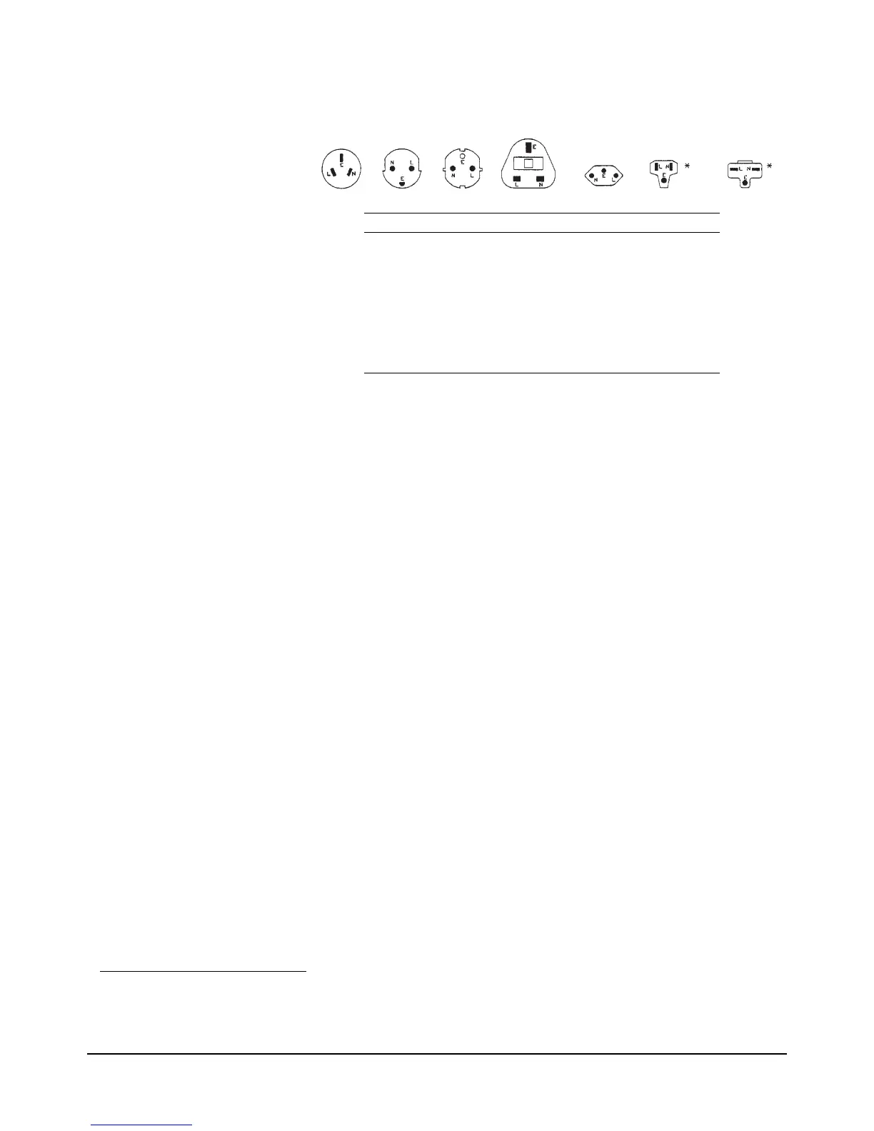
Australia Denmark Europe Great Brittain Switzerland U.S.A U.S.A.
Country Part Number Option Voltage
Australia 8120-1369 901 250V 6A
Denmark 1820-2956 912 259V 6A
Europe 1820-1689 902 250V 6A
Great Brittain 1820-1351 900 250V 6A
Switzerland 1820-2104 906 250V 6A
United States 1820-1378 903 120 10A
United States 1820-0698 904 240V 10A
Power cords supplied by Agilent have polarities matched to the power input socket
on the instrument.
NOTE:
Plugs are viewed from connector and. Shape of molded plug may vary
within country
*CSA certification includes only these power cords
Figure 3. Power Cords
1. GPIB (General Purpose Interface Bus) is an implementation of IEEE Standard 488-1978 and ANSI MC 1.1.

 Loading...


