Chapter 3 Configuring for Measurements 51
The multimeter will be damaged if any of the above maximum
non-destructive inputs are exceeded.
Guarding The measurement connection illustrations in this chapter show the
multimeter's Guard terminal connected to the low side of the measurement
source (guarded measurements). This configuration provides maximum
effective common mode rejection (ECMR) on the input terminals selected by
the Terminals switch, assuming the Guard switch is in the Open (out)
position. For non-guarded measurements, depress the Guard switch (TO
LO position) and do not connect the Guard terminal to the measurement
source. In the TO LO position, the Guard switch internally connects the
Guard terminal to the LO Input terminal on the terminals selected by the
Terminals switch. This configuration provides reduced ECMR.The
specifications in Appendix A shows the ECMR for guarded measurements.
We recommend high impedance, low dielectric absorption cables for all
measurement connections.
Suspending
Readings
In the multimeter's power-on state, the trigger arm, trigger, and sample events
are set to AUTO (these events are discussed in detail in Chapter 4). This
causes the multimeter to continuously take readings. Prior to configuring the
multimeter for measurements, you should suspend readings. Suspending
readings decreases the amount of time required for configuration and
prevents the possibility of undesired readings being placed in reading
memory or the GPIB output buffer. You can suspend readings by presetting
the multimeter (discussed next) or by setting the trigger arm or trigger event
to HOLD as follows:
OUTPUT 722; "TARM HOLD"
or
OUTPUT 722; "TRIG HOLD"
After configuring the multimeter, you can enable measurements by changing
the trigger arm or trigger event from HOLD to some other event. (Refer to
Chapter 2 for more information on triggering measurements).
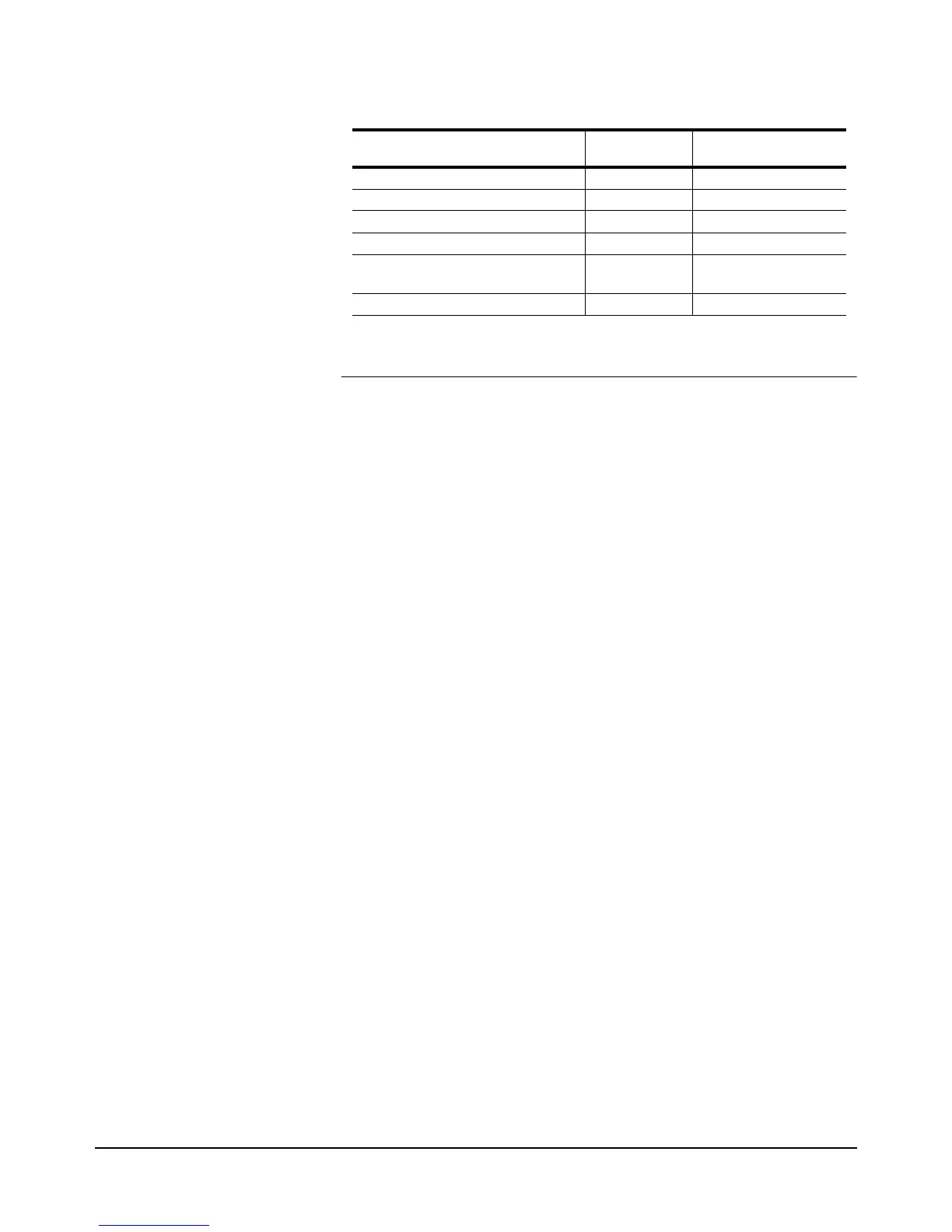
HI/LO W Sense to LO Input: ± 200V peak ± 350V peak
HI to LO W Sense:Input: ± 200V peak ± 350V peak
LO Input to Guard: ± 200V peak ± 350V peak
Guard to Earth Ground: ± 500V peak ± 1000V peak
HI/LO Input, HI/LO W Sense, or I
terminal to earth ground:
± l000V peak ± 1500V peak
Front terminals to rear terminals: ± l000V peak ± l500V peak
Table 9: Input Ratings
Rated Input Maximum Non-
Destructive Input

 Loading...


