34 Rockwell Automation Publication 442L-UM005B-EN-P - April 2017
Chapter 3 Configurable Functions
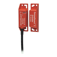
In Figure 10, if the protective field (3) or the warning fields (2) stretch as far as
a wall or another object (pillar, neighboring machine, shelf ), there must be a
distance of 100 mm (3.94 in.) between the protective field or warning field and
the object to help prevent false triggering (1).
Figure 10 - Configure Protective and Warning Fields
Protective or Warning Field Suggested by the Safety Laser Scanner
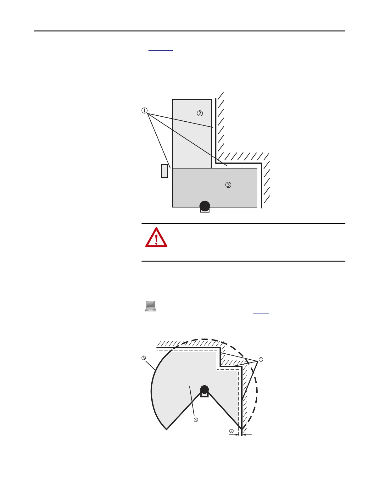
Figure 11 - Reading the Protective Field
ATTENTION: Secure unprotected areas.
If it is possible to access a narrow strip between the protective field and a
wall or another object, you must protect this strip with additional measures
(for example, fence or floor protection).
The SCD software can suggest the protective or warning field in the field set editor. The safety laser
scanner scans the visible surrounding contour several times. From the data that is obtained, the SCD
software suggests the contour and size of the field. Figure 11 shows an example for the reading of a
protective field.
 Loading...