Rockwell Automation Publication 442L-UM005B-EN-P - April 2017 67
Application Examples and Connection Diagrams Chapter 6
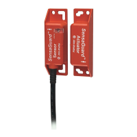
Restart Interlock and External Device Monitoring
SafeZone Mini device with relays/contactors; operating mode: with restart
interlock (universal I/O 1 must be configured as reset) and external device
monitoring (universal I/O 2 must be configured as EDM).
Figure 43 - Connection Diagram with Restart Interlock and External Device Monitoring
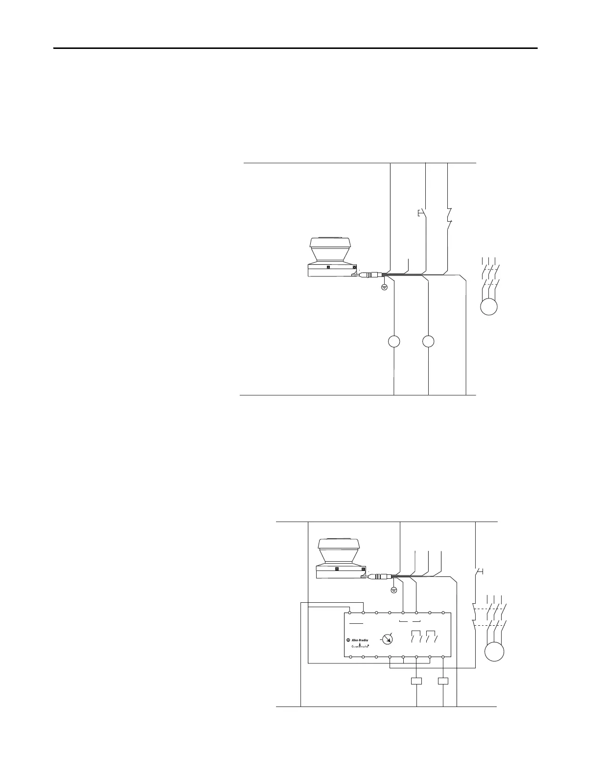
SI Guardmaster Safety Relay
SafeZone Mini device in combination with a SI Guardmaster safety relay:
operating mode of SafeZone Mini device is ON/OFF and SI safety relays is
configured for monitored manual reset.
Figure 44 - Connection Diagram in Combination with a GSR SI Safety Relay
SafeZone Mini
Shld
wire
Brn Yel***Grn**
BluGry Pnk
Wht*
Color Pin Signal
Wht 1 Output - Warning Field1*
Brn 2 +24V DC
3 Universal I/O1** (Reset)
Yel 4 Universal I/O2*** (EDM)
Gry 5 OSSD 1
Pnk 6 OSSD 2
Blu 7 0V DC
Shld 8 Earth Ground
Reset
K1
K2
K1
K2
* Not congured for this application
* No Connection
** Software Configu ed for Reset input
*** Software Configu ed for EDM
+24V DC
0V DC
L1
M
L2 L3
K1
K2
Grn
A2A1
+
-
S11
S21
S12
S22
L11
Y32
S34 13
13
14
14
23
23
24
24
24VDC
IN1
SI
RESET 0
MM
AM
K2
Reset
K1
K2
M
24V DC
0V DC
Monitored Manual Reset
SafeZone Mini
Shld
wire
Brn
Yel *
Grn*
Blu
Gry
Pnk
Wht*
Color
Wht
Brn
Grn
Yel
Gry
Pnk
Blu
Shld
Pin
1
2
3
4
5
6
7
8
Signal
Output-Warning Field1*
+24V DC
Universal I/O1*
Universal I/O2*
OSSD 1
OSSD 2
0V DC
Earth Ground
* not configured for this
application
no connection
L1
L2
L3
K1
 Loading...